After my first baby steps into the retro-computing world with a ZX81, I thought I should add a new member to the family. In memory of the late Lord Sinclair, it had to be a ZX Spectrum, and nothing else.
![]()
Sourcing a Sinclair ZX Spectrum
I did not own a ZX Spectum myself, but used it, played with it and programmed it at a friend’s (the same that had a ZX81. He migrated to a Spectrum something like a year later, around late 1982 or early 1983)
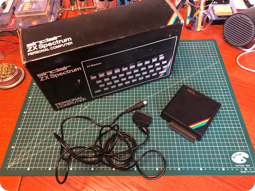
I had good luck last time with Leboncoin. Finding a “Speccy” on this site is pretty easy. I found a nice offer (less than 90€), with a boxed ZX Spectrum, a manual and a joystick expansion. We stroke the deal. Unfortunately, the seller couldn’t send the package in time, so the deal was automatically cancelled after a week of waiting. I then searched for another ZX Spectrum, and found one, a bit more expansive, but in its original package, sold along with a Peritel (french for SCART connector) expansion and cables.
Deal was done, the package arrived home a week later:
Unboxing
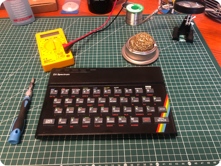
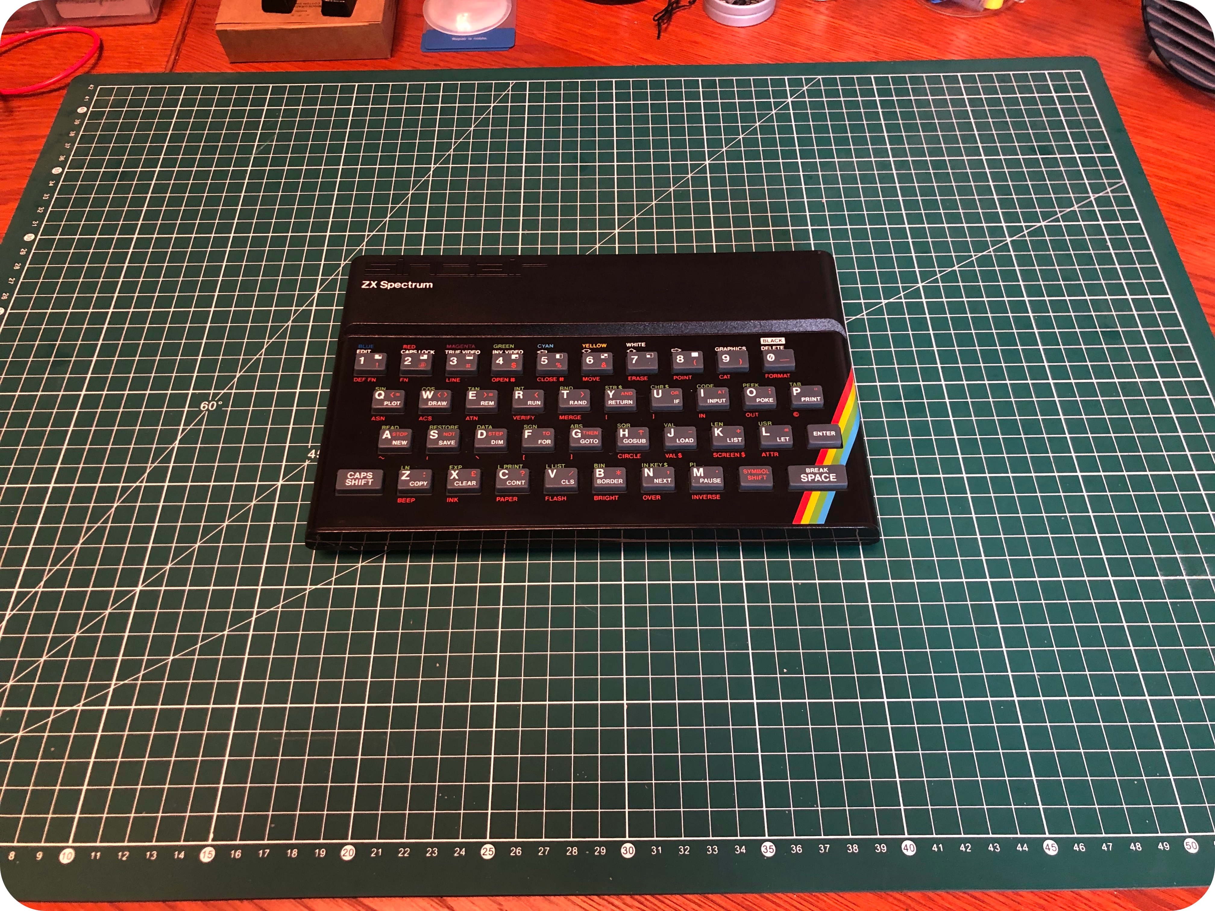
The ZX Spectrum is smaller than I remember. Surely because I was around 11-12 years old when I used one. Compared to the ZX81, it is almost as wide, a little less deep, but much heavier.
Overall, the ZX Spectrum I got was in good conditions. A bit dirty, especially the rubber keyboard (traces of some kind of glue on a few keys), a few stains on the case, but almost no scratches on the keyboard metal plate:
Like its little brother, this Speccy didn’t smell particularly good. The previous owner might have been a smoker. From the outside, no signs of corrosion though.
Opening up the ZX Spectrum
Let’s flip the ZX Spectrum, then remove and store the 5 screws from the back:

Gently separate the top and bottom parts of the case. You will then see a pair of ribbon cables, connecting the PCB to the keyboard:
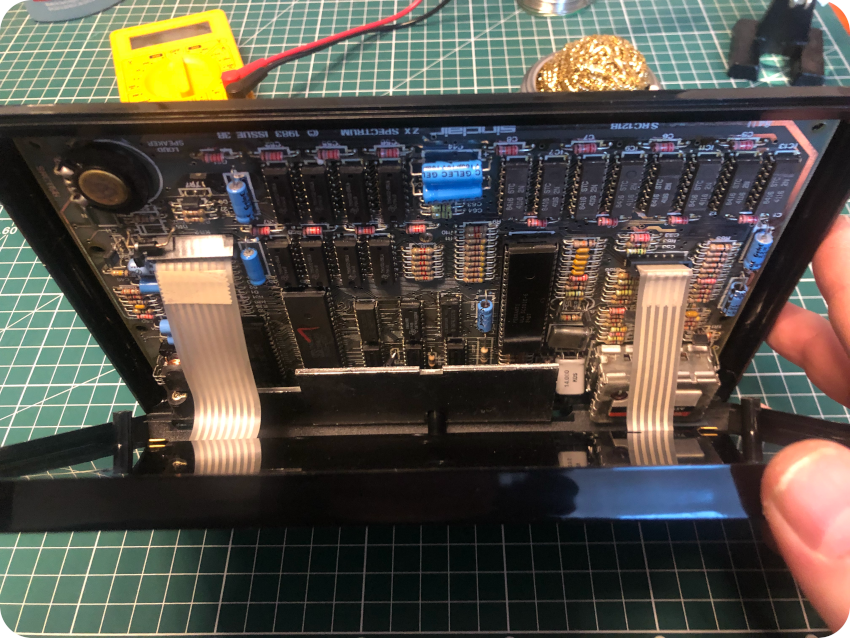
Just like for the ZX81, these ribbon cables don’t age well and break apart very easily. You can grip each of them close to the connectors and carefully pull them free:
Both of the ribbon cables were in perfect conditions. And I did not break them (they were easier to pull than the ZX81’s).
The last screws from the PCB can now be removed, as well as the large metal shield bolted next to the voltage regulator.
The plastic case is now ready for a soapy bath and a good scrub with a toothbrush. Once dried, an anti-static cleaner was applied to both parts with a micro-fiber cloth. Stains were removed. The rubber keyboard was then scrubbed and cleaned. I did not removed it from the case, but could remove the glue that on some of the keys without damaging them.
The ZX Spectrum PCB
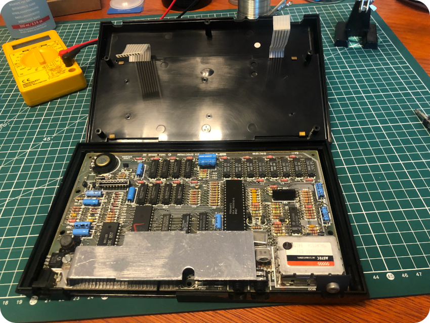
Let’s take a look at this ZX Spectrum’s PCB. It is more complex than the ZX81’s, but still easy to understand:
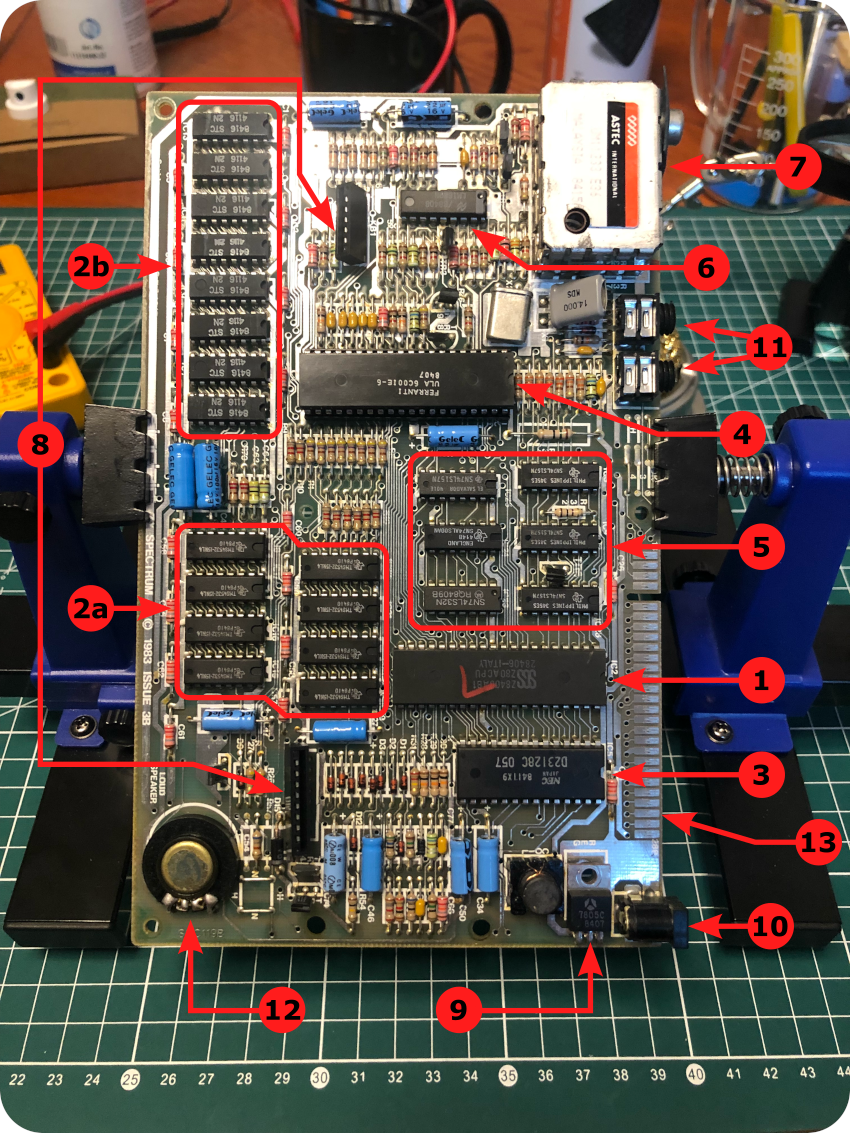
There have been many revisions of the ZX Spectrum PCB. This one is an “issue 3B” board, built around:
- Microprocessor: the Sinclair ZX Spectrum uses Zilog Z80 8-bit microprocessor, clocked at 3.5MHz (thus, a tiny bit higher than the ZX81). The one used here was manufactured by SGS
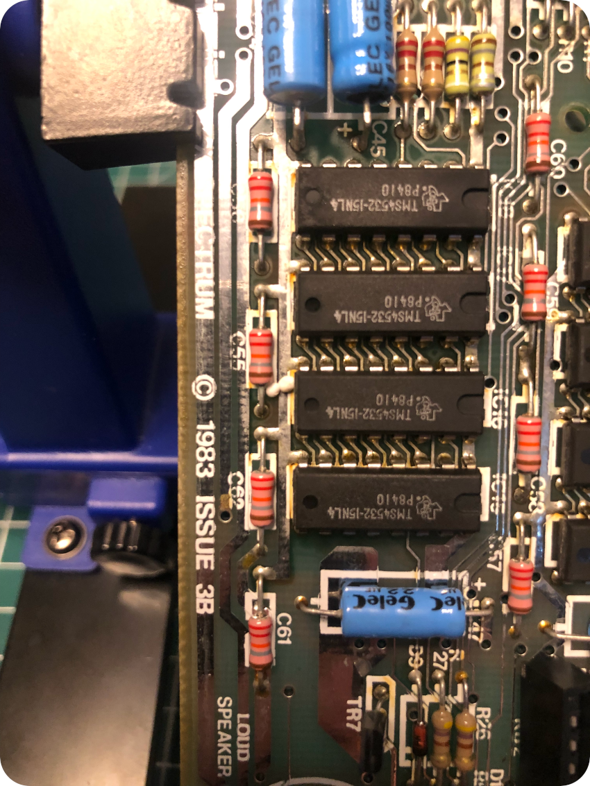
- RAM: originally, the Spectrum had 16K or 48K of RAM. This issue has two types of RAM chips installed. The Lower 16K (location 2b) is composed of 8 x 8416 STC 4116 2K DRAM chips. The Upper 32K (location 2a) is composed of 8 x TMS4532-15NL4 DRAM chips, manufactured by Texas Instruments. This should give a total of 64K instead of 32K, but only one half had passed the manufacturing test and they were sold as 32K chips for a good price (on pin needing to be set to select the proper page of RAM cells). It’s typical of Sir Clive Sinclair cost optimization. The total onboard memory is thus 48K (Lower 16 + Upper 32) on this ZX Spectrum
- ROM: the board has 16K of ROM, manufactured by NEC
- ULA (Uncommitted Logic Array): it uses a Ferranti ULA 6C001E-6. It is a later, debugged revision of earlier designs (5C102E, 5C112E, 6C001E-5). Thus, the board does not require ugly mods, like the ‘cockroach’ (a 74LS00 chip hand soldered on top of the PCB with flying lead connections) or the ‘spider’ (a ZTX313 transistor soldered over the CPU) mods. The 6C series also runs cooler than the previous 5C series
- Logic gates: 6 x SN74X ICs, manufactured by Texas Instruments and Motorola. I don’t have much details on these unfortunately …
- Video Modulator: a LM1889 IC, manufactured by National Semiconductor, designed to interface audio, color difference and luminance signals to TV antennas
- TV Output Modulator: the board uses an ASTEC International UM 1233 E36 RF Modulator to generate signals for UHF Televisions
- Keyboard connectors: these two are used to connect the keyboard ribbon cables to the PCB
- Voltage regulator: the board uses a 7805 voltage regulator manufactured by Thomson-CSF. It is coupled to the rather large metal heat sink I removed earlier on
- DC Power: 9V DC power connector
- Jack connectors: EAR and MIC connectors, to be connected to a tape recorder
- Speaker: unlike it’s mute baby brother, the ZX Spectrum could actually generate sound (1 channel, 10 octaves, I believe)
- Connector slot: the Speccy has a connector slot on the back of the case, enabling various expansions (SCART connector, Joystick ports, Printer, ZX Microdrive, …)
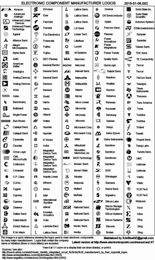
Note: to identify the IC’s manufacturers, I used this handy logo sheet:
Inspecting and cleaning the board
I inspected the back and the front of the PCB, looking for bad solder joints, corrosion, bad / cut traces or leaks. I took a particular intention to the radial electrolytic capacitors, that were all looking good:
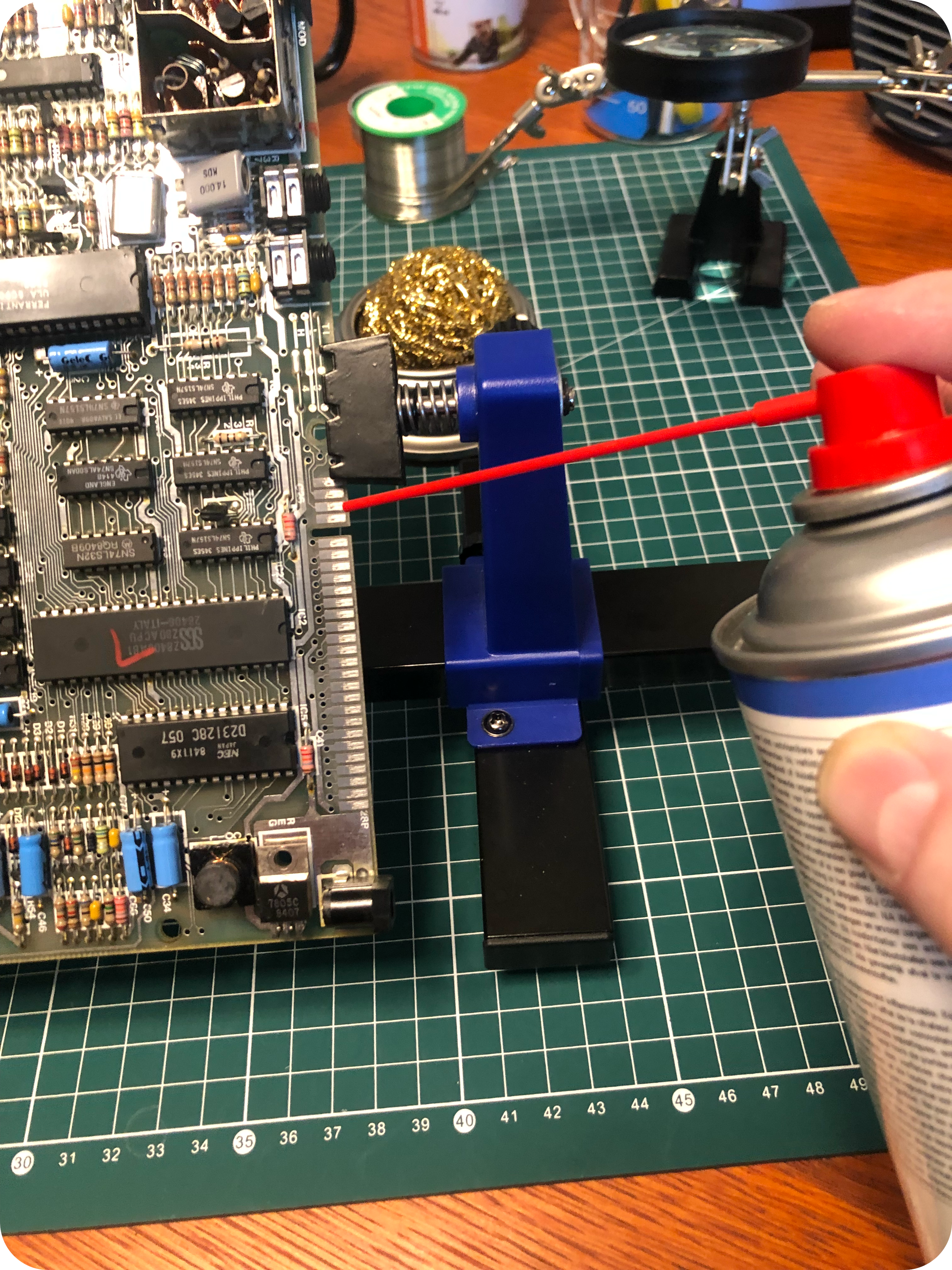
I then cleaned both sides of the PCB with Isopropyl Alcohol, and cleaned all the connectors with a contact cleaner:
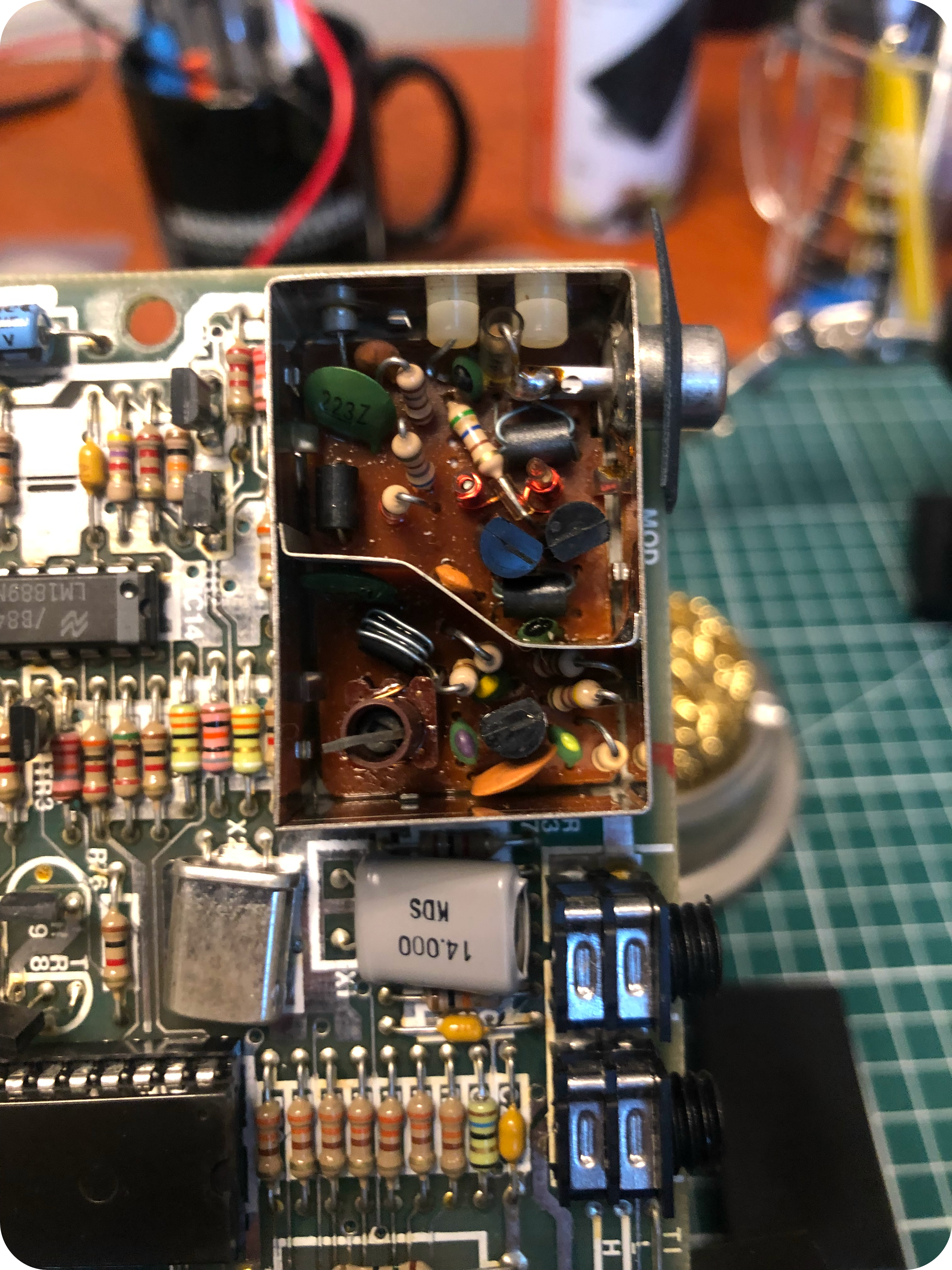
I then opened up the RF modulator to inspect its components. No signs of modifications (like a composite mod for example), everything looked good and unspoiled:
A quick test and … next steps
In the meantime, both parts of the plastic case had dried. And since the PCB was inspected and cleaned, I carefully reassembled the Speccy.
The case is clean, shiny, smelling fresh and proud of Rick Dickinson‘s glorious industrial design:
Even though I did not yet inspect nor clean the SCART expansion, I wanted to give this Spectrum a try. I hooked it to my old 42″ Samsung TV, via the SCART expansion, crossing finders to see it working.
I had hang this LED TV to a wall of the room I use for remote-office a few months earlier. This is the room where I also set up my bench to work on vintage electronic devices. I thought this 10-15 years old TV may prove to be handy for testing these, since it has HDMI, SCART, VGA, analog + digital antenna and composite inputs.
Indeed, to a my surprise, after messing a bit with the TV input and picture parameters to select the right input source, then to display, zoom and scale the video output properly to its original 4/3 format, I was greeted with this vintage but familiar welcome :
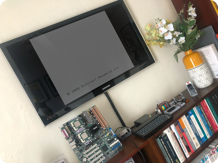
The video quality is actually worse than what this scaled down picture shows. But, frankly, I had never used the SCART interface of this TV before, and wasn’t even sure this would work. Maybe I am lucky. But I’m quite happy it worked.
Still, I will probably invest in an OSSC (or maybe a RGBtoHDMI interface) later on, expecting from it a better picture quality, and better compatibility with the other vintage devices I am thinking of playing with.
Next steps ?
- Cleaning and inspecting the SCART expansion
- Recapping the board with new electrolytic capacitors
- Have fun with it !
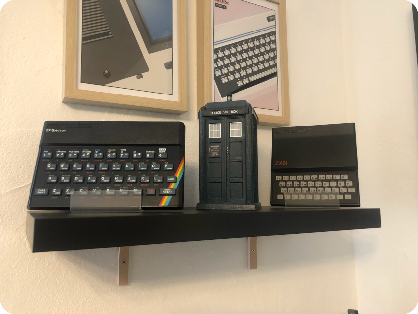
Meanwhile, it is time for a little Sinclair family reunion. And time to meet a friendly TARDIS, as a tribute to the British culture from a frog-eating Frenchman.
Oh, and speaking of British computers, I bought an Amstrad CPC 464. I had to. Really.
But that’ll be the subject of a next post …