France is a strange country. We tend to argue about anything. Nonsensical – yet tenacious – “troll wars” have been raging for years, for the naming of delicious viennoiseries or … for which is the best 8bit home computer. Indeed, when I was a kid in the early 80‘s, such “wars” were raging: Thomson vs Matra-Hachette vs Oric vs Sinclair …
But, as far as I was concerned, the real fight was Amstrad CPC 464 versus Commodore 64:

I chose a side. I was on the Amstrad CPC team. Retrospectively, let’s be frank, for no other reasons than the facts that it was cheaper and generally more available in France than the C64. But, must of all, because I had friends owning an Amstrad and none owning a Commodore 64.
In this nonsensical state of mind, it meant that Oric‘s and Sinclair‘s were OK-ish, but old news. Thomson‘s were for schools and teachers. Matra-Hachette‘s were nowhere to be found and subject to mockery. Apple‘s were for rich kids born with a silver spoon in hand. Amstrad was the King. And Commodore sucked.
All of this was of course troll talk, unfair and untrue. Commodore 64 were good computers. Excellent ones. True milestones in the history of home computers.
40 years later … I still love my Amstrad CPC 464. Yes, it is still my favorite vintage computer. It always will be the case. But, as a retro-computer enthusiast, I love my Sinclair ZX81 and Spectrum, as much as I love my Apple IIc, my Oric Atmos or my Matra-Hachette Alice 90. But the fact remains … I had never, till this day, touched a Commodore 64.
How sad and pathetic is that ?! I feel like I missed for no reasons an enormous part for the computer history. Christmas was around the corner. It was time for peace and about time to welcome home a Commodore 64.
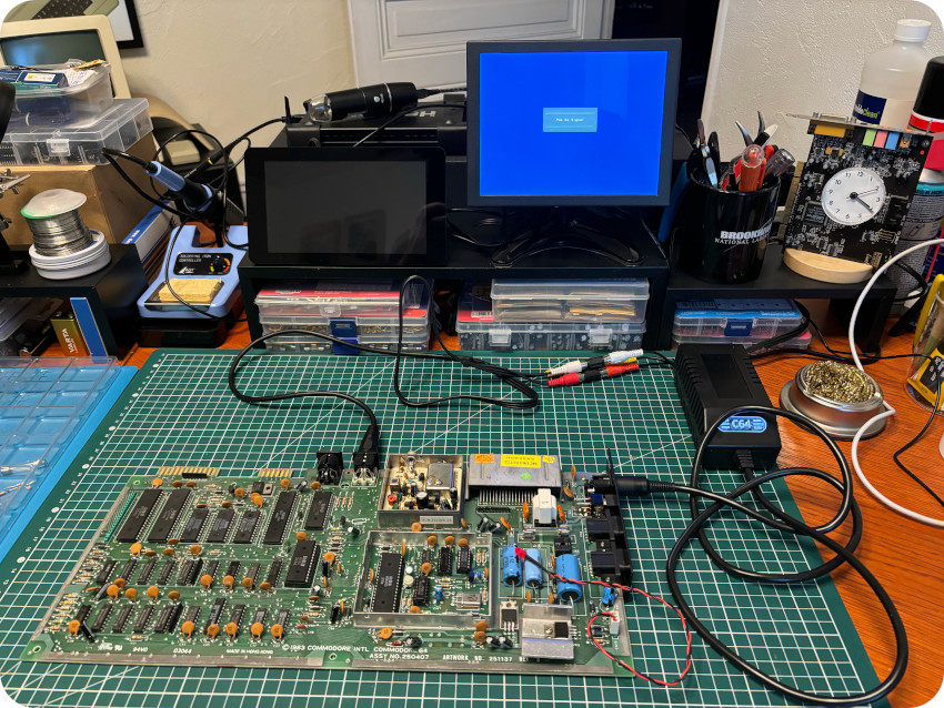
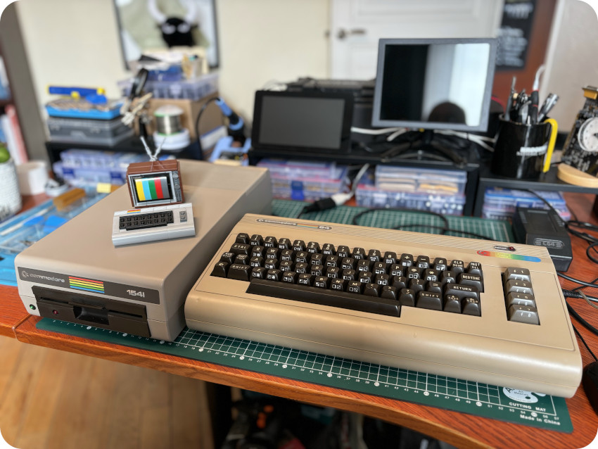
![]()
This is a long blog post, so, to ease navigation, here is a table of contents:
- Introduction
- Sourcing a Commodore 64
- Unboxing
- PROCEP
- The Power Supply Unit
- Cleaning the case
- Taking care of the keyboard
- Removing PROCEP’s mods
- Cleaning the motherboard
- The PCB (ASSY 250407)
- Building an Audio-Video cable (composite)
- First run (and fail)
- Analysis
- Voltages
- Signals
- Replacing the VIC-II
- 1541 drive : first run (and fail)
- Cleaning the 1541 drive
- Servicing the 1541 drive
- The 1541 PCB
- 1541 drive (second run)
- Sunbrighting (part 1)
- Cartridge (ROBCOM Combi-Turbotool+)
- Software
- Future proofing
- Sunbrighting (part 2)
- More software and XUM1541
- Null Modem cable and Internet Access
- Wrap up
- Next steps
- Acknowledgments, huge thanks & links
Note: this order of this table of contents was laid out so that the blog post makes as more sens as possible. In reality, some of the listed tasked were started in parallel and/or in disorder since they were spread over 6 months, with sometime a lot of time / waiting in between.
INTRODUCTION
Commodore Business Machines has a particular place in the history of home computers. Founded in 1954 in Toronto, Canada, by legendary entrepreneur Jack Tramiel, Commodore transitioned from typewriters (in the 50’s), to calculators (in the late 60’s) then to home computers in the 70’s.
Indeed, in the late 70’s Texas Instruments, the leading provider of calculator components at the time, entered the market directly. They introduced a series of machines priced below the manufacturing cost of Commodore’s corresponding parts. This pushed Jack Tramiel to acquire MOS Technology in order to assure his supply.
Chuck Peddle, who was heading the design of the 650x family of processors at MOS, became Commodore’s head of engineering. He convinced Jack Tramiel that calculators were a dead-end business, and convinced him to focus instead on personal computers. This move gave birth to the Commodore PET (“Personal Electronic Transactor”, though sometimes nicknamed “Peddle’s Ego Trip” … because of Chuck Peddle’s personality). The PET was announced at the 1977 Hanover Fair:
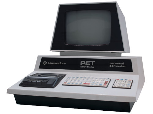
The impact on the market was so strong, that, together with the Apple II and the Tandy Radio Shack TRS-80, the PET formed what was later called the “1977 Trinity“:
By 1980, Commodore was one of the largest micro-computer companies. The PET, originally priced at $795 with 8kB of RAM and it’s all-metal enclosure, was primarily used in school. There, its ability to share printers and disk drives over a local network shined. But the PET did not compete well in the home computer sector. Chuck Peddle had brutally left Commodore for Apple (for a short time), then created Sirius Systems Technology, where he created the Sirius 1 (also known as the Victor 9000). A new team, lead by Michael Tomczyk, designed the VIC-20 to address a home computer mass market. Announced in 1980, it was sold in retail stores in 1981 at the price of $299:
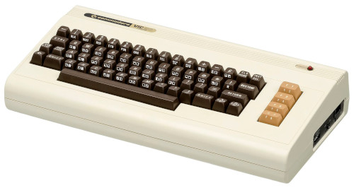
With the VIC-20, Commodore became the first computer company to ship more than one million units. Over the VIC-20 lifetime, it is estimated that 2.5 million units were sold.
The Commodore 64 (or C64) was introduced at the 1982 Consumer Electronics Show:
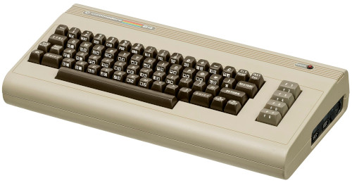
Originally code-named “VIC-40” as a successor to the VIC-20, the Commodore 64 finally took its name from its 64K of RAM. It shared its iconic “bread bin” form factor with the VIC-20. Its hardware was designed by Yash Terakura, Bob Russell, Bob Yannes, David A. Ziembicki and Shiraz Shivji (who, later on, will be the primary designer of the Atari ST, when Jack Tramiel was ousted of Commodore and acquired Atari).
It was a massive success. Some say the C64 played a role comparable to the Ford Model T automobile, in introducing a novel technology to middle-class households through innovative and cost-effective mass production. By the end of its lifetime, it is estimated that 12 to 17 millions units were sold worldwide. This is wild ! It dominated the low-end computer market, with 30-40% of the US Market for example. It was a major hit in Germany, including a specific version for the discount supermarket chain Aldi.
In the UK, it was a little harder, as it faced competition from the Sinclair ZX Spectrum, the BBC Micro, the Dragon 32, and later on the Oric Atmos and the Amstrad CPC 464.
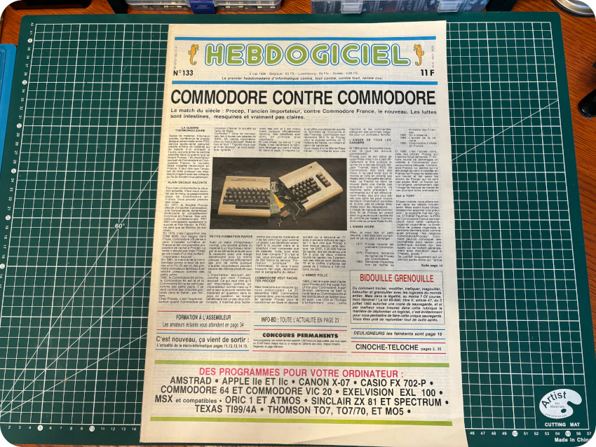
The story was similar in France where it faced British computers, but also local competitors such as the Thomson TO7. On top of that, distribution and adaptations to the French market were given to PROCEP. This French company was in business with Commodore since 1977 and the PET era. They had exclusive rights from Commodore, and doing well. Until 1985, where Commodore created Commodore France. This did not end well, including legal fights between Commodore France and Commodore importer PROCEP, as titled by French magazine Hebdogiciel #133 “Commodore vs Commodore“:
The difference in France with Amstrad was striking. Amstrad France was created in 1982 and was lead at the time by Marion Vannier. Without any computer background, she did a tremendous job, and CPC464’s sold like hot cakes in France (over 200 000 units per month at its launch at the end of 1984). This may be one of the reasons why the C64 was less successful in France when compared to other countries.
But … back to the Commodore 64. During its long lifetime (1982-1994 !), there have been many variations. Here are some of the most noticeable ones:
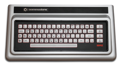
- Commodore MAX: in 1982, Commodore released the Commodore MAX in Japan as a game console. Note: it was called “Ultimax” in the USA and “VC-10” in Germany.
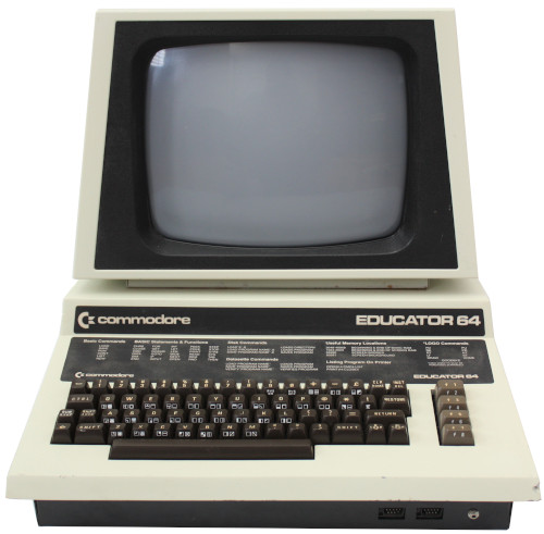
- Commodore Educator 64: in 1983, to address competition from the Apple II on the US education market, Commodore launched the Educator 64 with a PET-like all-metal design:
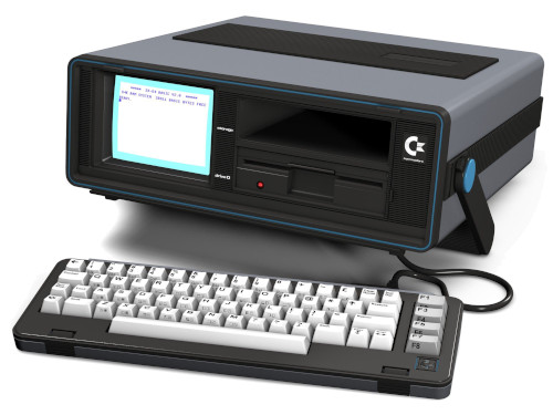
- Commodore SX-64: in 1983, Commodore launched the SX-64, a portable version of the C64 (first commercial color “portable” computer):
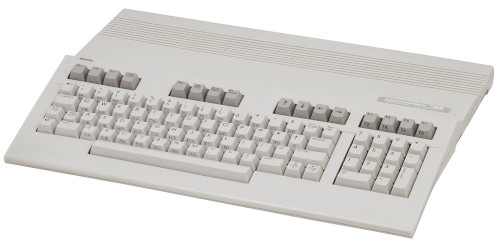
- Commodore 128: the Commodore 128 (and Commodore 128 D, it’s desktop variation, resembling the Amiga 1000) were successors to the C64, released in 1985. They are nearly full compatible with the Commodore 64. Though adding improvement to the C64, they had to face competition with 16/32-bit computers like the Atari ST or the Commodore Amiga;
- Commodore 64C: In 1986, Commodore launched the Commodore 64C, with revision on the hardware and a design close to the Commodore 128, breaking with the “bread bin” original design:
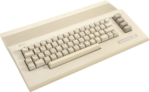
Note: there were other variations, like the C64G – launched in 1987, with a cut-down version of the electronics and a bread bin design (but slightly clearer colors and white keys), or the Commodore 64 Game System in 1990.
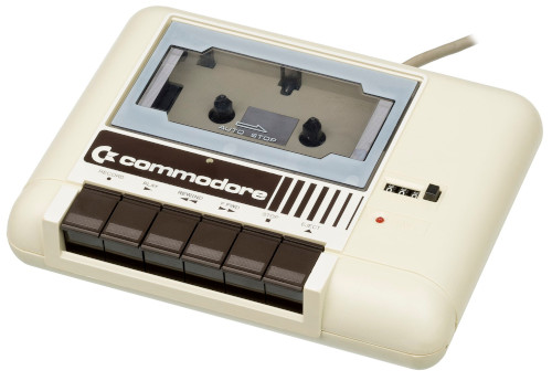
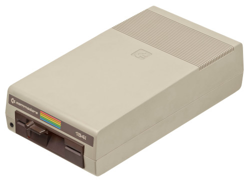
The Commodore 64 used various external peripherals. For example, let’s name a few storage peripherals:
- The Commodore 1530 Datasette:
- The Commodore 1541 Floppy disk drive:
Nowadays, the legacy of the C64 lives on, with software emulation (like VICE for example), Linux-based recreations (including the full-size THE64) or FPGA-based hardware (like the MiSTer). It is even possible to build a Commodore 64 from scratch with brand new PCB’s, IC’s, as well as shells and keys recreation !
SOURCING A COMMODORE 64
As I usually do, I searched on LeBonCoin web site for a Commodore 64 lot. I was looking for a “bread bin” Commodore 64 and a floppy disk drive.
I wasn’t in a hurry, so I took my time. In the beginning of November 2023, I found a nice lot, with a boxed Commodore 64, a 1541-II floppy disk drive and a joystick. All in very good conditions, with cables and PSU, at a very reasonable price. I bought the lot … but, unfortunately, without any answer after 3 days, the deal was automatically cancelled. Later on, the dealer removed its offering from the web site.
One month later, I found another offering that suited my needs. This time, a boxed Commodore 64, in perfect conditions, with its manual, a few floppy disks, but no floppy disk drive. I was a bit more pricey, but I bought the lot nevertheless. And … after a few days, without answer, the deal was also off. Damned !
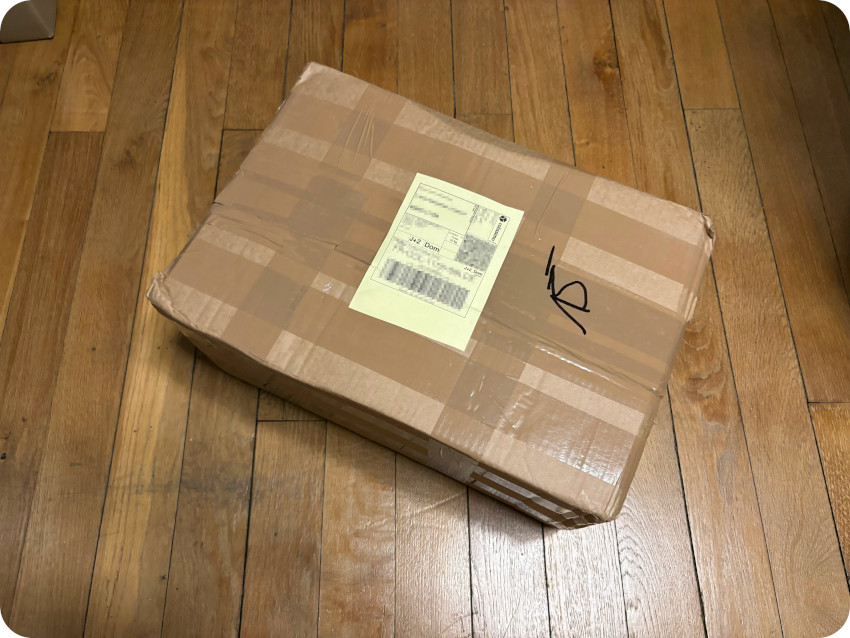
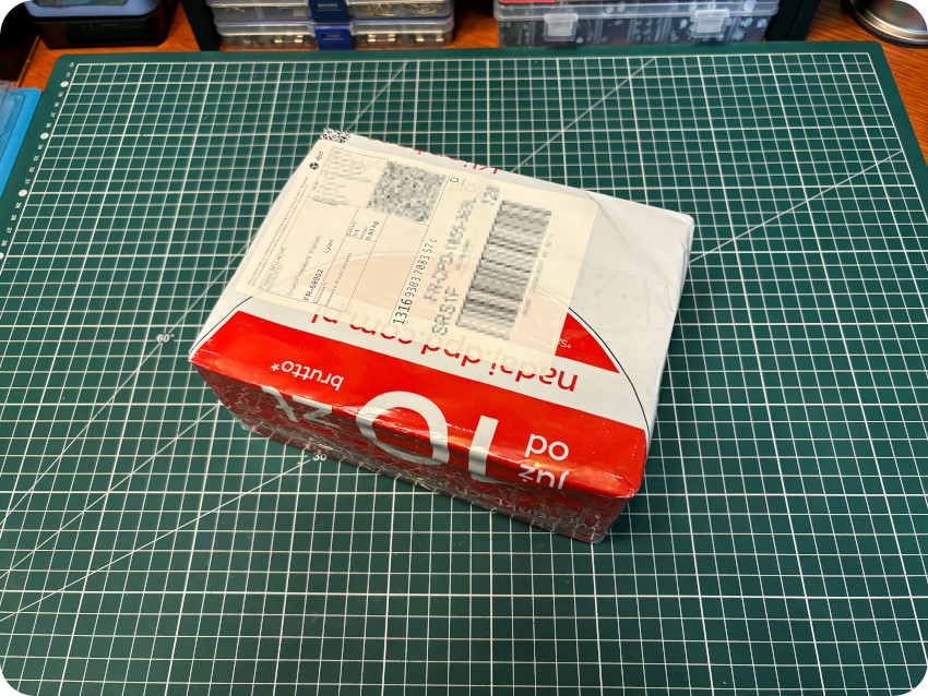
I really wanted a Commodore 64 for Christmas. I guess I’ll never really be a grown up … so, I kept hunting. By mid-December, I found another interesting lot, with a Commodore 64, a 1541 floppy disk drive, an unknown cartridge, a few cables, floppy disks in a box, a couple of boxed games and the external PSU. In poor external shape, but at a very reasonable price. I struck the deal, and … a few minutes later, got an answer. The packages was shipped the next day, and I received it on the 20th of December, right on time for a retro Christmas treat !
UNBOXING
Since I was on a meeting at CEA Paris-Saclay when the parcel arrived, I unboxed it the next day:
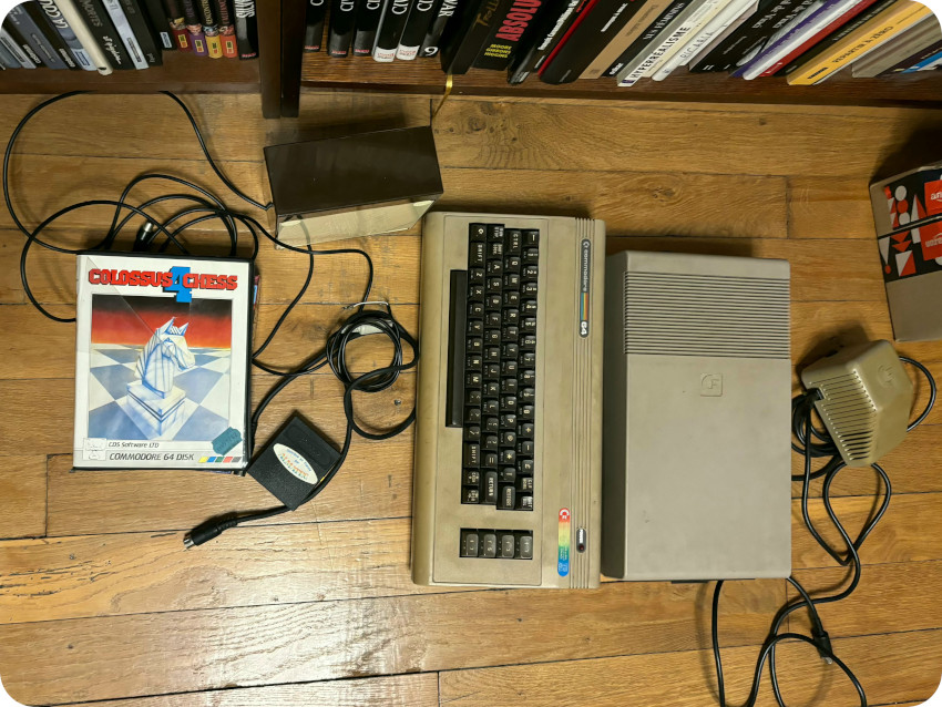
The lot included:
- A well packed (but really filthy) Commodore 64, bubble-wrapped
- A well packed Commodore 1541 floppy disk drive, bubble-wrapped
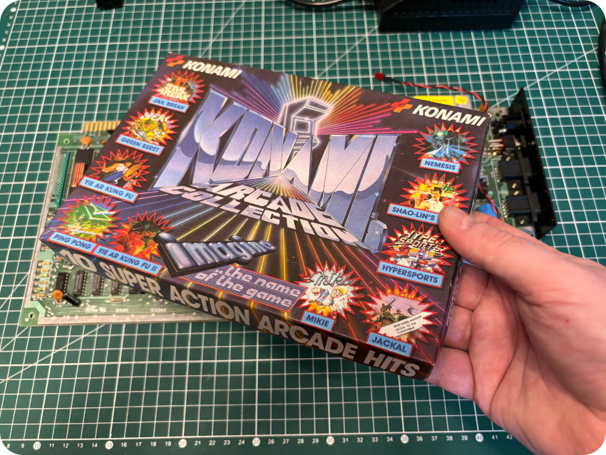
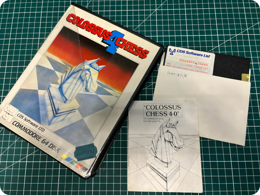
- Two boxed games: Colossus Chess 4 (CDS Software) and Konami’s Arcade Collection (with Jail Break, Green Beret, Yie Ar Kung Fu, Yie Ar Kung Fu II, Ping Pong, Nemesis, Shao-Lin’s Road, Hypersports, Mikie and Jackal)
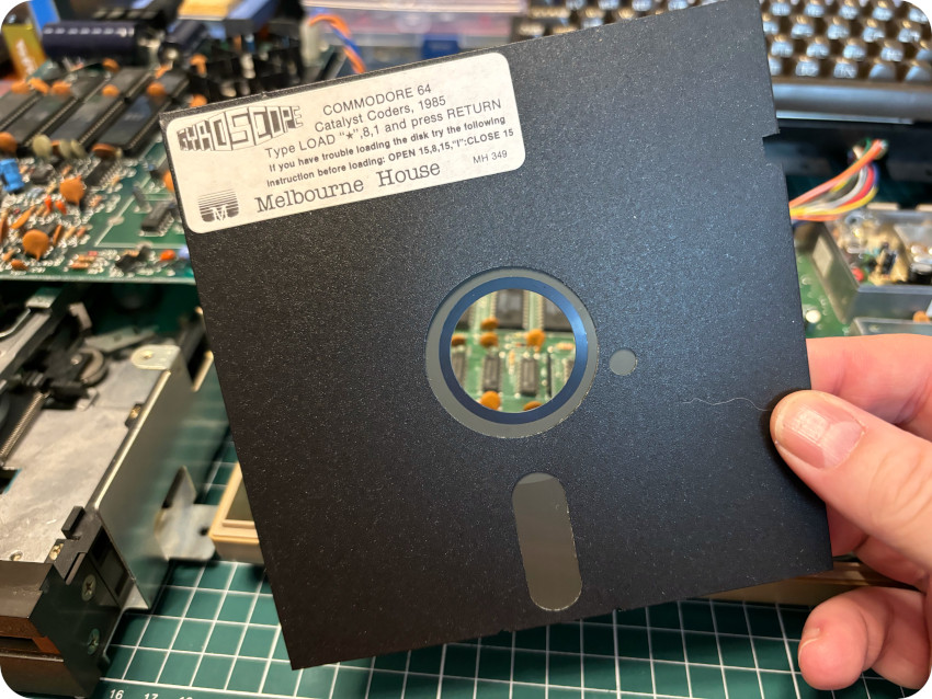
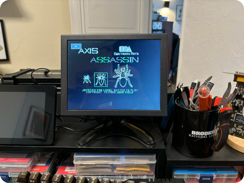
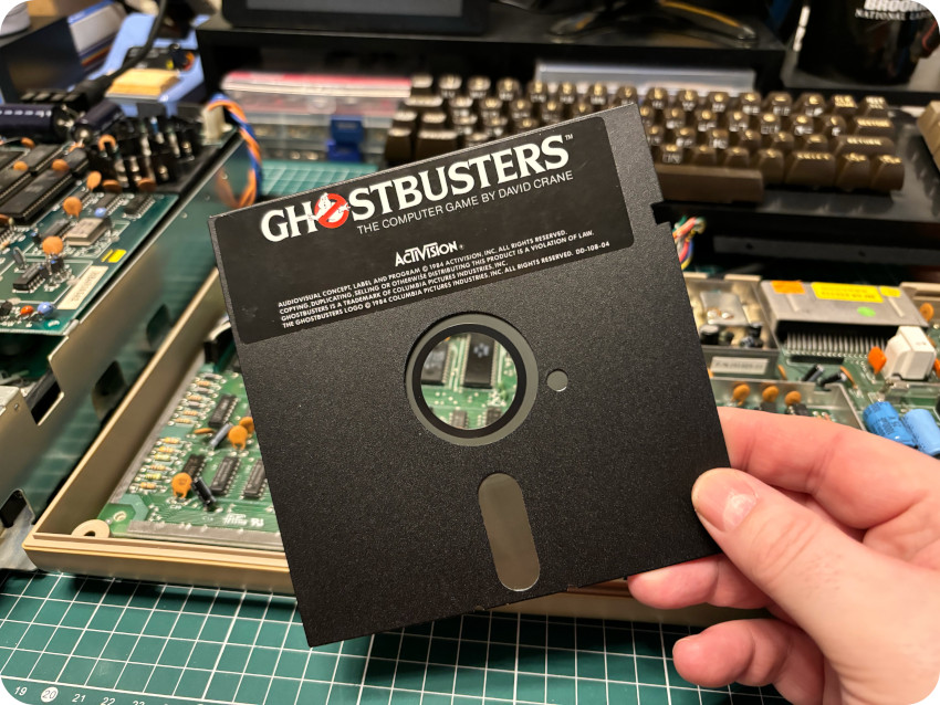
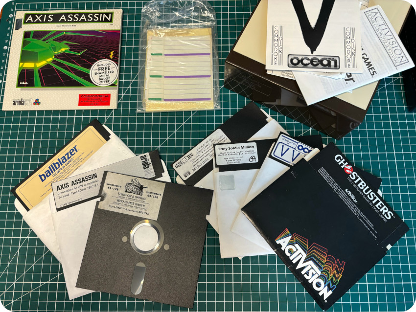
- A box of floppy disks, which turned out to be original games in excellent conditions: Ghotsbusters (Activision), Axis Assassin (Electronic Art), V (Ocean), Gyroscope (Melbourne House), Ballblazer (Activision), They Sold a Million game compilation (Beach Head, Daley Thompson, The Staff of Karnath, Jet Set Willy), ZZap! Sizzlers game compilation (Thing on a Spring, Who Dares Wins, Dropzone, Wizard’s Lair)
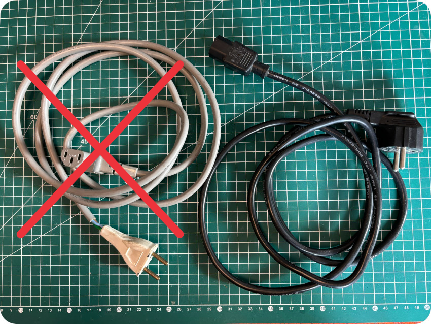
- A Power Supply Unit for the Commodore 64 (in very poor conditions)
- A power cord for the floppy disk drive (in very poor conditions)
- Something that looks like an TV antenna cable
- An IEC serial cable
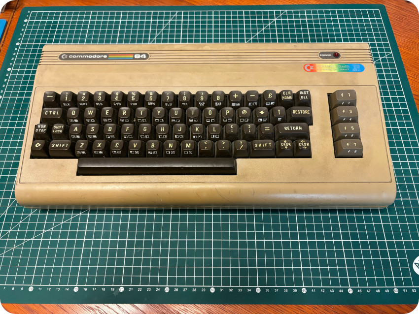
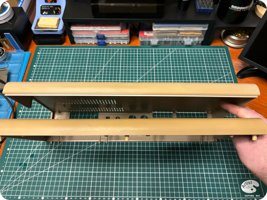
I unwrapped the Commodore 64 and put it on the bench:
- This was, from far, the most gross looking retro-computer I ever bought. From the smell, the last owner must have been a heavy smoker. The case is yellowed on the front, as well as some of the keys. The top shell is utterly filthy …
- Nothing broken externally. But, by the sound of it, there was something loose or broken inside the case !
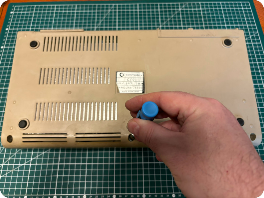
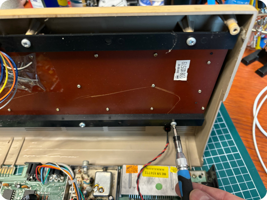
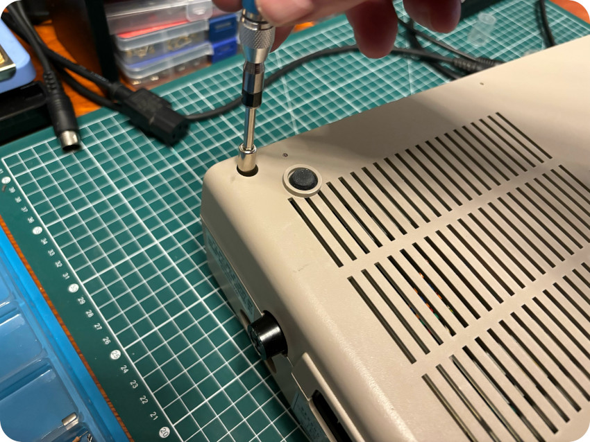
Since, I am always anxious when it comes to shipping, I decided to open the Commodore 64 right away to check whether something was damaged during transport.
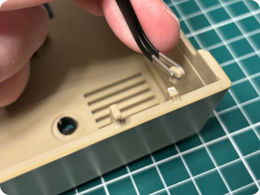
Opening the case is a matter of removing 3 screws on the front. Be careful nevertheless ! The back of the case is maintained by 6 small plastic tabs that snap off very easily: two of them broke off, two were already missing (leaving only 2 in place)
I opened up the Commodore 64 and found:
- Two (long) loose screws
- A loose card, seating on the cardboard shield, wired to the motherboard
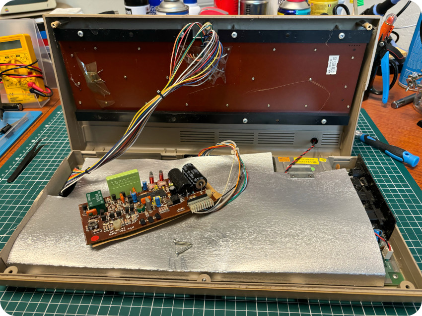
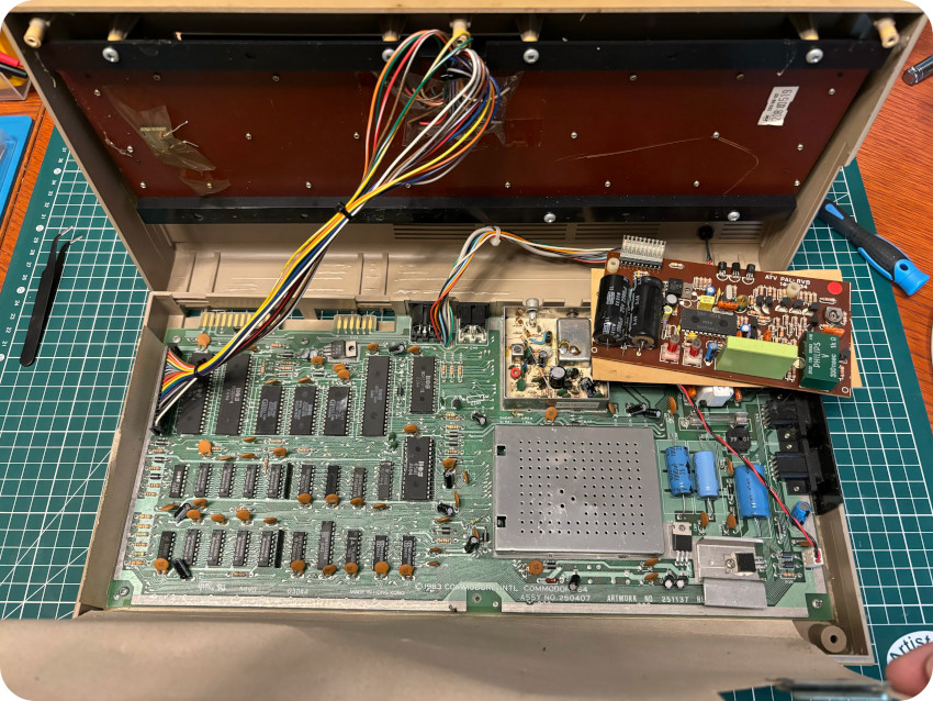
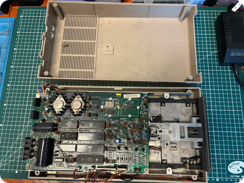
I pulled off the cardboard shield to have a quick look at the main PCB:
- The RF modulator is missing its top metal cover, revealing some modifications inside
- No leaky capacitors. The PCB itself, unlike the case, is (almost) clean and seems to be in good shape
- From the markings on the card (ATV PAL RVB), it is related to video output. It had been soldered on the back to the motherboard.
What are these modifications ? What is this card ? I am really not familiar with Commodore 64’s, so let’s investigate !
PROCEP
I googled around, dug out a few old magazines, and asked the always nice and knowledgeable folks from system-cfg.com.
Here is a little backstory. PROCEP was a French company, founded by Elie Kenan. He was representing MOS Technology in France in the late 70’s, when Commodore acquired MOS Technology. As such, he had the opportunity to meet Jack Tramiel and, as the PET launched in 1977, PROCEP was created in order to distribute the PET in France. Later on, PROCEP distributed the VIC-20, and the Commodore 64. Around 1985, Commodore France was created, and the relationship between Commodore and PROCEP turned sour. This was the end of the road for PROCEP, which went belly up around 1987. In the meantime, Jack Tramiel had been kicked out of Commodore and bought Atari. And … Elie Kenan joined force with Atari France, and ended General Manager for Atari US, Canada and France.
During the 1977-1985 era, PROCEP did more than distribute Commodore computers in France. They adapted them to the French market, providing:
- French AZERTY keyboards for the PET,
- Hard drives and professional software suites (“Propaye”, “Procompta”, …) for pro users,
- Printers with French accents,
- Translations of documentations,
- Modifications for French video standards compatibility
Indeed there were different standards for analog color televisions, depending of countries. The three majors ones were:
- NTSC (“National Television System Committee”) – and sometimes called “Never Twice the Same Colors”, originating from the USA,
- PAL (“Phase Alternating Line”), originating from Germany, but first used in the UK,
- SECAM (“Séquentiel de couleur à mémoire”) – and sometimes called “Surtout Eviter la Compatibilité Avec le Monde” (Above all, avoid compatibility with the world), originating from France.
The following map pictures the different NTSC, PAL and SECAM “regions”:
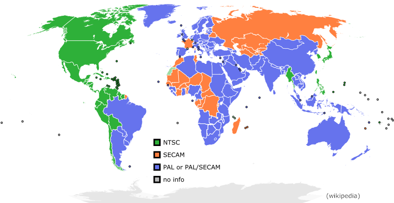
Commodore produced only two versions of the C64: for NTSC and PAL regions. There were no version for SECAM regions.
Dual PAL/SECAM analog television sets where not widely. Thus, PROCEP designed, manufactured and integrated modifications for the French market, based on the PAL Commodore 64 version (they also designed mods for the VIC-20 at the time). PROCEP distributed two “modded” versions of the C64 (pictures from http://www.mapetitecollection.com):
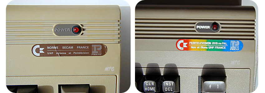
The left one, labelled with a brown sticker (SECAM), was – from what I understand – the most common one. My C64 is of the second version (SCART RGB/PAL), on the right. They are labelled with a rainbow sticker. It was also possible to use an external PROCEP decoder, even rarer I believe.
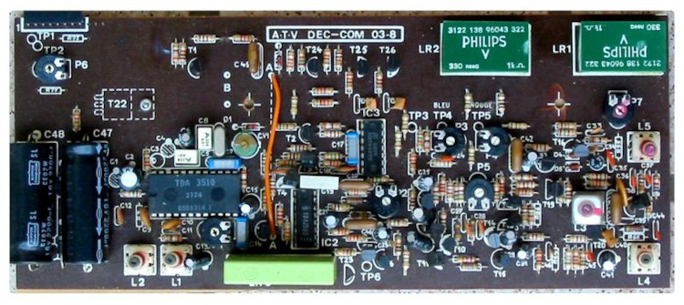
SECAM and RGB versions used specifically designed boards:
- The ATV DEC-COM (picture from https://www.c64-wiki.de) : this extension card was soldered to the motherboard and attached under the keyboard. It allowed to produce a video signal conforming to the SECAM television standard.
- The ATV PAL-RVB (picture from https://www.c64-wiki.de) : it was also soldered to the motherboard and attached under the keyboard (though mine was loose). This card was used to generate an RGB signal.
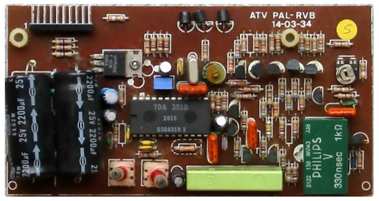
As we will see later on, these also involved modifications to the motherboard: a few traces were cut, a capacitor was removed, the RF modulator was customized, etc.
What shall I do with this mod ? This is a difficult question … On one hand, one could argue that it is better to keep the hardware as close at it were from factory. On the other hand, historically speaking, modded C64 were, in France, the way they were distributed by PROCEP.
In the end, I decided to reverse the modifications because:
- technically speaking, the modification is not useful anymore,
- the quality of the signal out of the mod wasn’t great (as far as I understood from more qualified people than myself),
- I had no video cable, and this mod modifies the pinout of the video connector. It would be easier to build or order a standard video cable,
- I had a hunch this C64 would not be fully functional. It would be harder to diagnose problems with the modifications in place.
Maybe I took the wrong decision. I really don’t know. Of course, I will keep the board safe, as an historical artifact. And if in time I would change my mind, it would still be possible to put the PROCEP mod back.
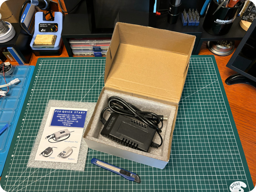
THE POWER SUPPLY UNIT
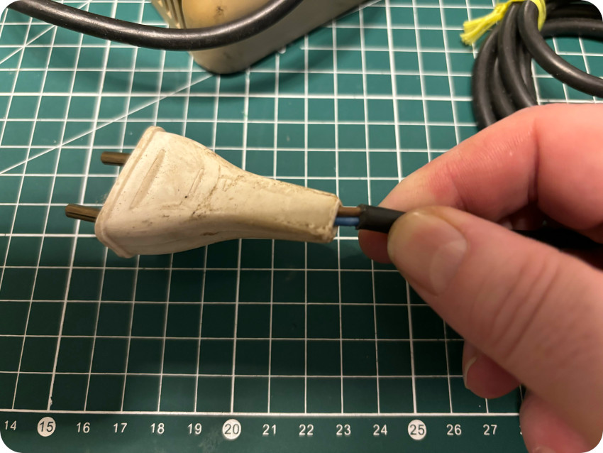
Let’s take a look at the external PSU included in the lot:
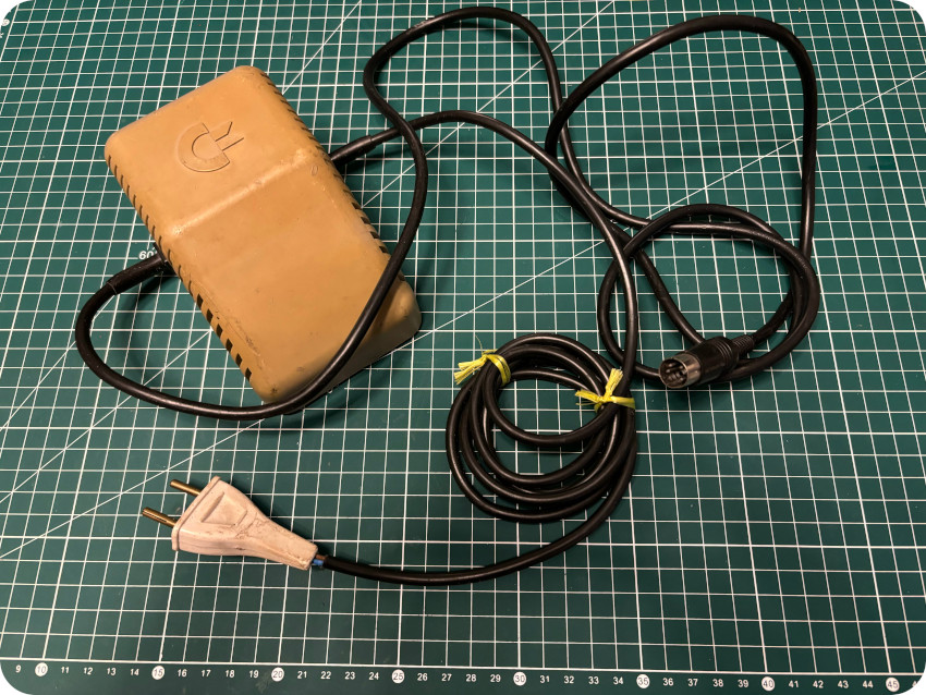
It looked really bad and unsafe:
C64 power supplies were made by different manufacturers. For example, European ones were usually provided by a German company named Ismet.
C64 PSUs provide +5V DC and 9V AC. Unfortunately C64 PSUs are known to fail very often. While the 9V AC line seldom breaks, the +5V DC often does, resulting in higher than safe voltages, that fried IC’s !
Given the known history of C64 PSU’s and the poor state of mine, there was no way I would use it to power my Commodore 64. I ordered a brand new one (AirDrive, on Amazon). It took about 4 weeks to come from Poland:
During this time, I had quite some of time to clean my Commodore 64 and familiarize myself with its electronics.
CLEANING THE CASE
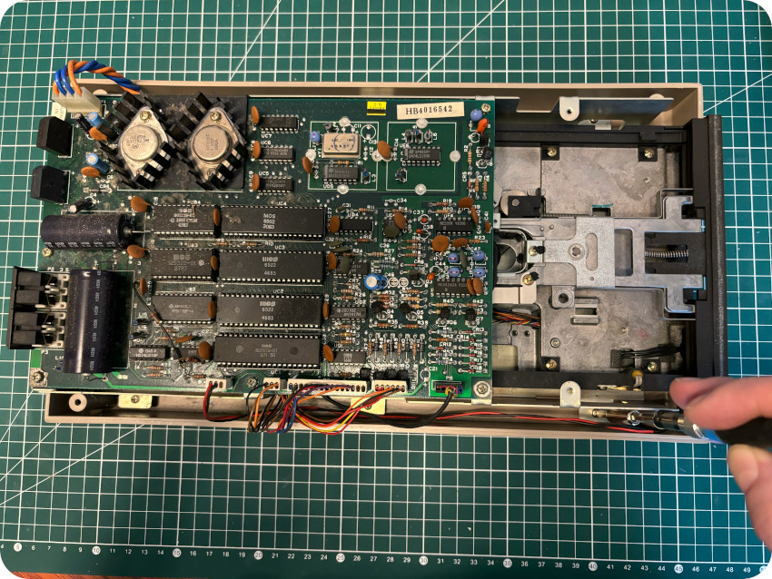
First, let’s unscrew the keyboard from the top shell:
Then, let’s unscrew the motherboard from the bottom shell, and disconnect the keyboard from the main PCB:
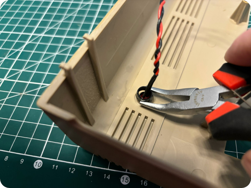
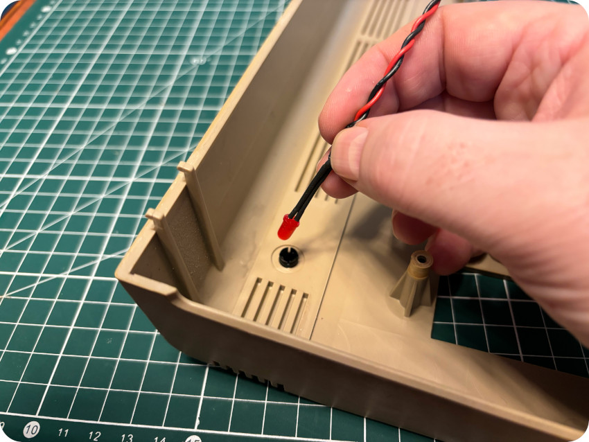
Finally, let’s remove the power LED from the PCB:
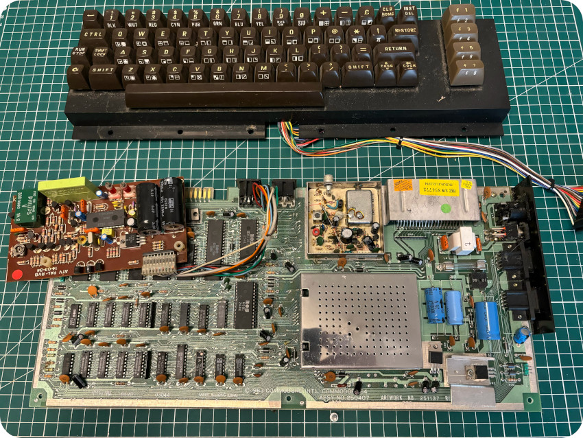
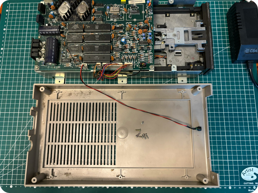
The motherboard and the keyboard are now freed from the case:
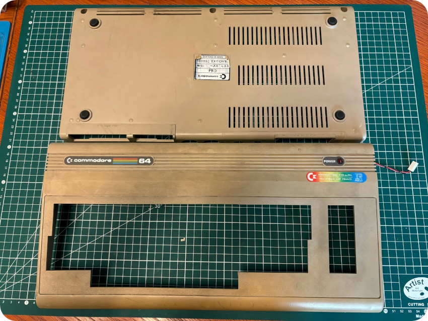
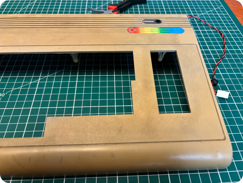
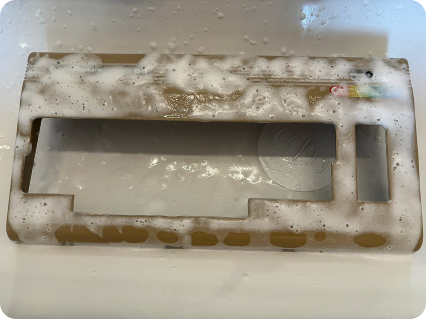
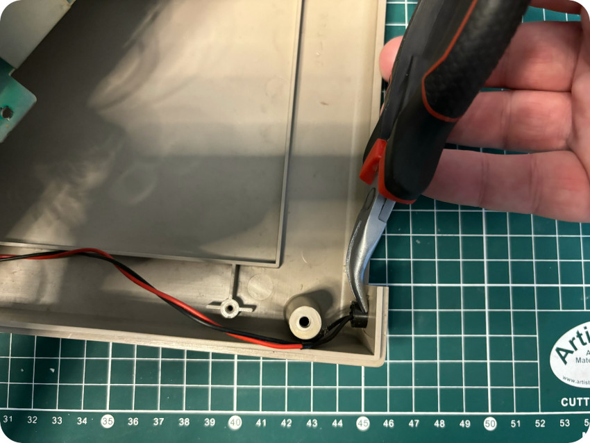
Let’s take a look at the enclosure. It was a mess. Smelly, utterly dirty, with a lot of scuff marks:
Let’s carefully remove the ring holding the power LED in place:
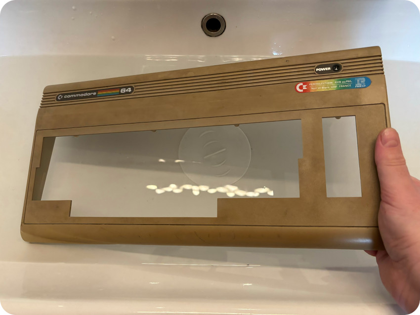
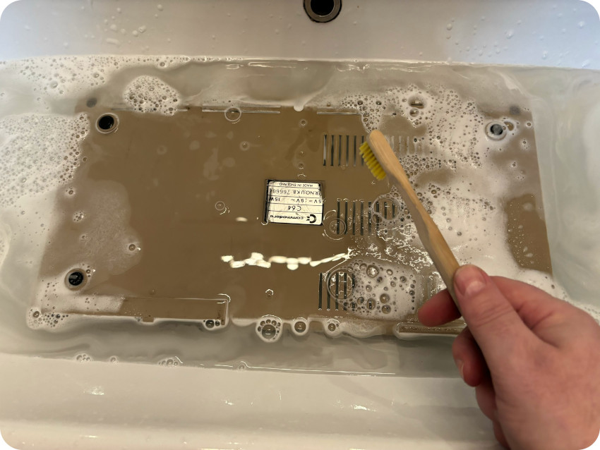
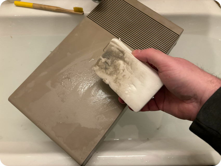
It was time for a bath in warm soapy water, cleaning foam and a lot of scrubbing:
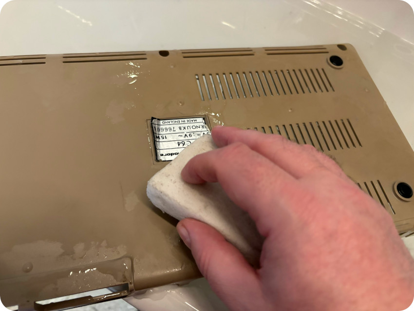
I erased the scuff marks with a magic eraser (which died in the process):
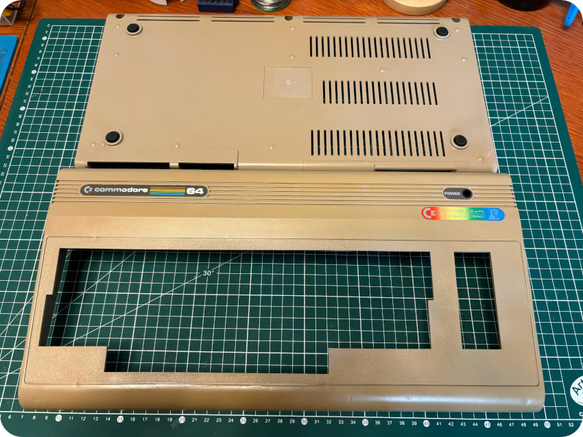
As usual, I finished the cleaning process with IPA, anti-static foam and a soft micro-fiber cloth. The final result is not that bad. Definitely not perfect, but the case looks (and smells) much better !
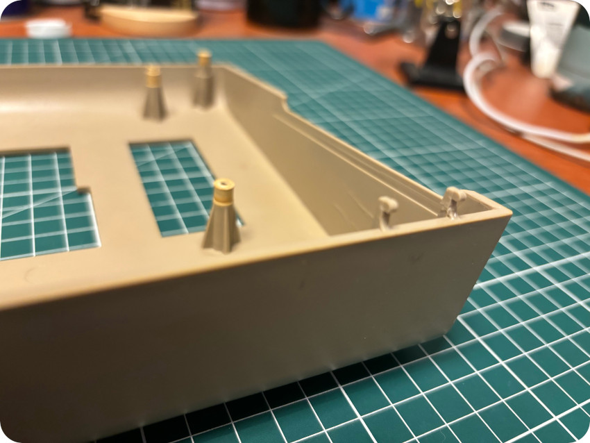
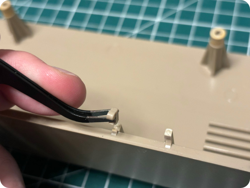
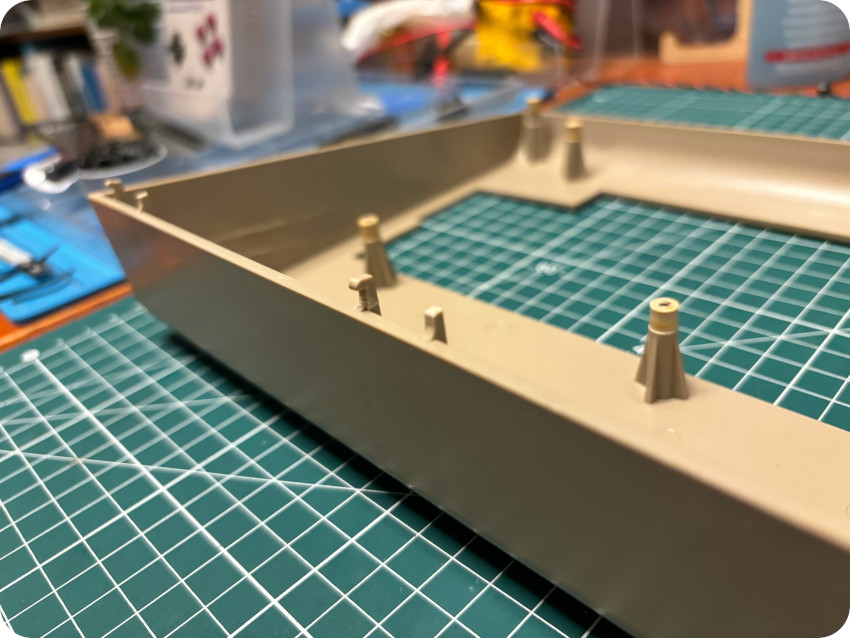
Now, let’s glue back the snapped tabs:
TAKING CARE OF THE KEYBOARD
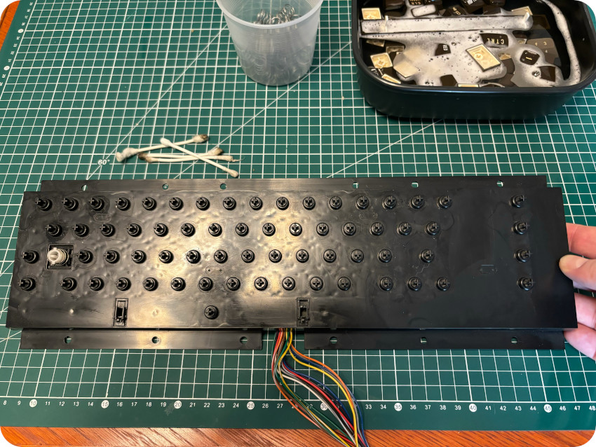
Let’s take care of the keyboard:
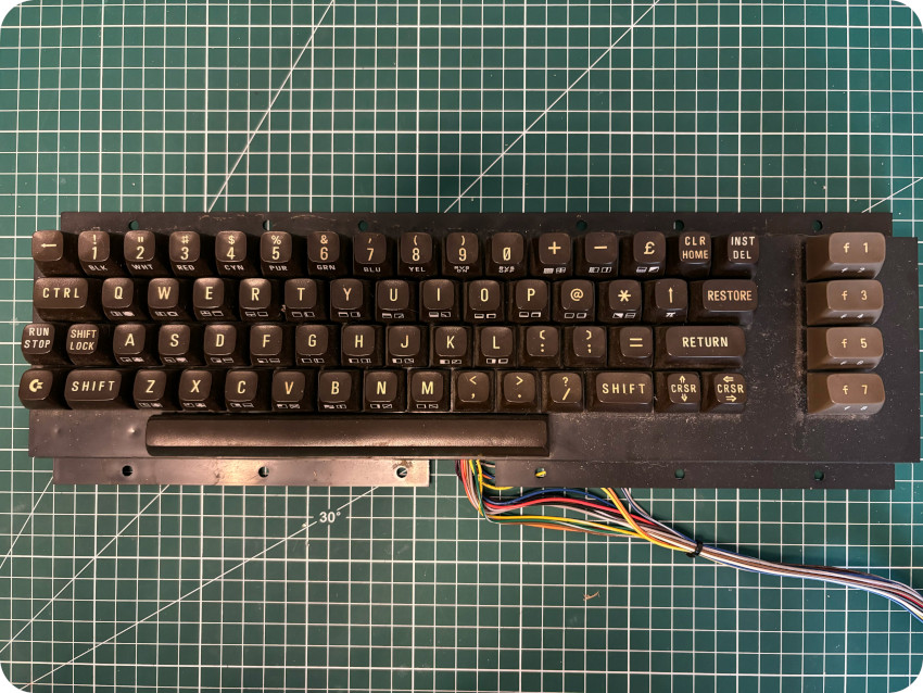
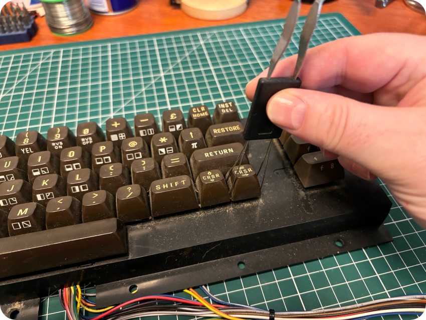
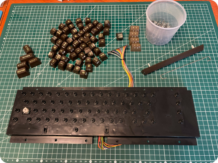
I removed the keys one by one, using a key cap puller, taking care of not losing the springs. I must say, when compared to most of 8bit computers I know, this keyboard feels very sturdy and high quality. Though the layout is a bit awkward, it feels much better than the Amstrad CPC464 keyboard, I have to admit. Some of the keys were a little stubborn, but, all in all, it went well.
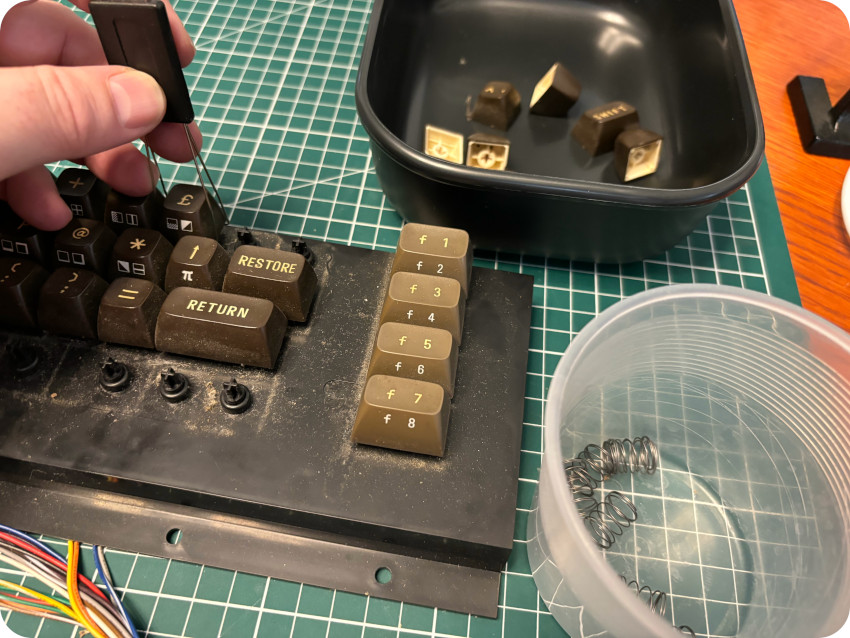
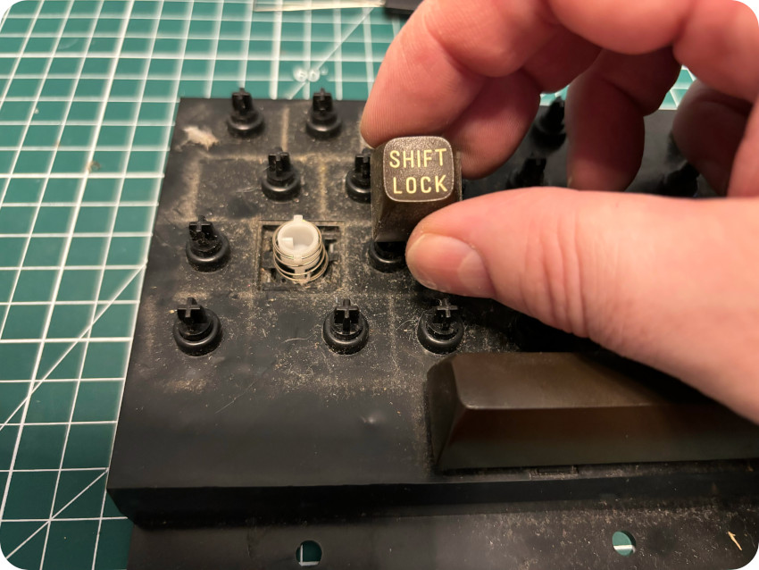
I took extra care of the “Shift/Lock” key mechanism (and its shorter spring), as well as the Space Bar and its stabilizer:
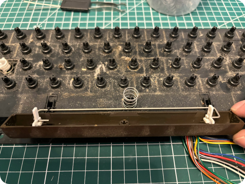
I removed the dust bunnies and other mummified insects:
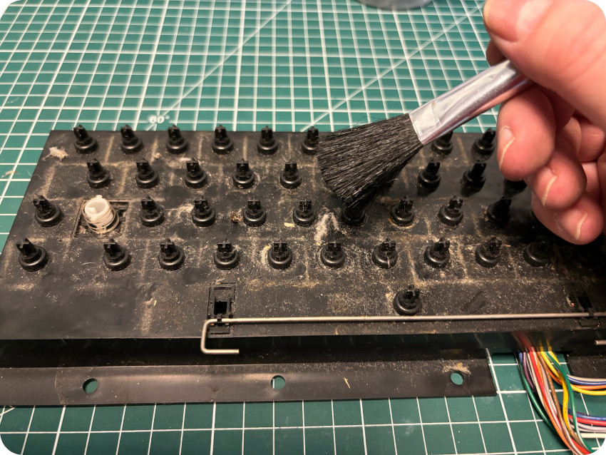
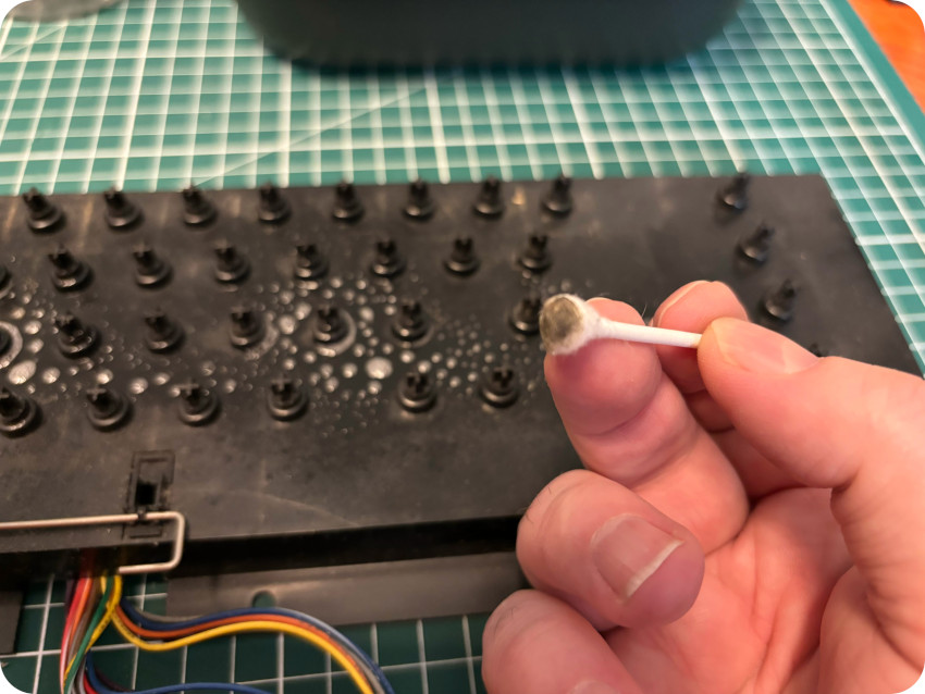
Then, I proceeded to a thorough (and needed) cleaning with (many) cotton swabs:
Meanwhile, the keys were bathing into warm soapy water and the springs were soaking into WD-40:
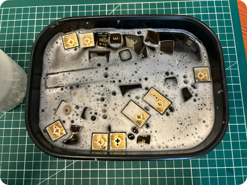
I cleaned up each keys with a micro-fiber cloth, and let the springs dry on towel paper:
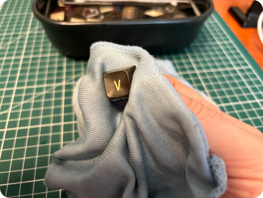
Here is the final result:
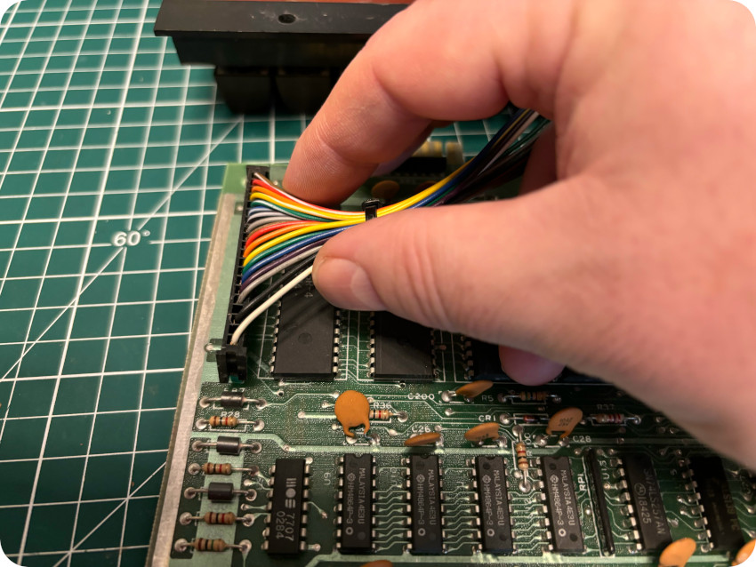
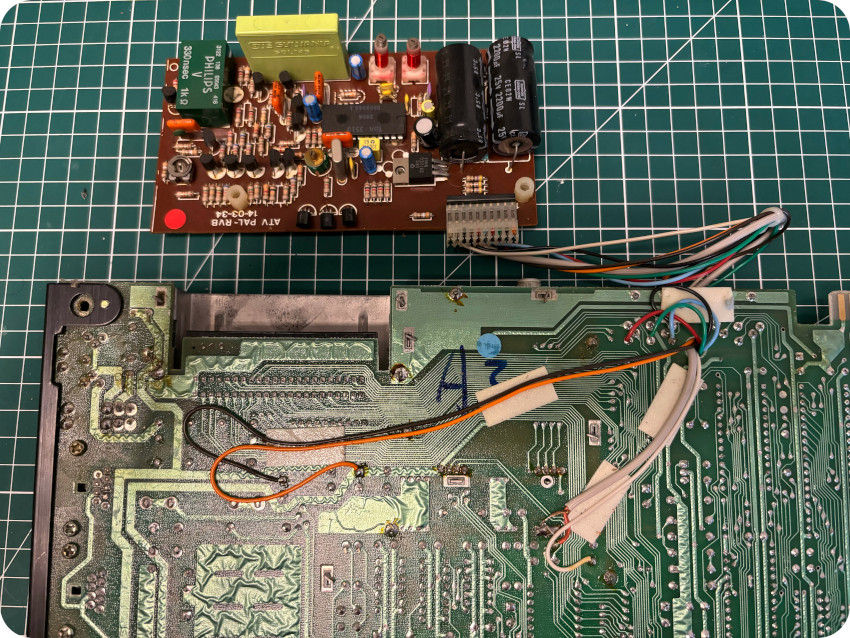
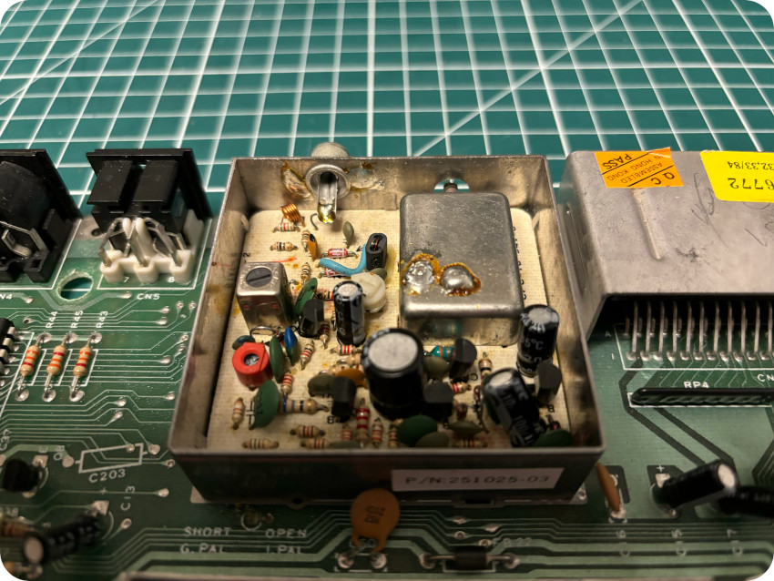
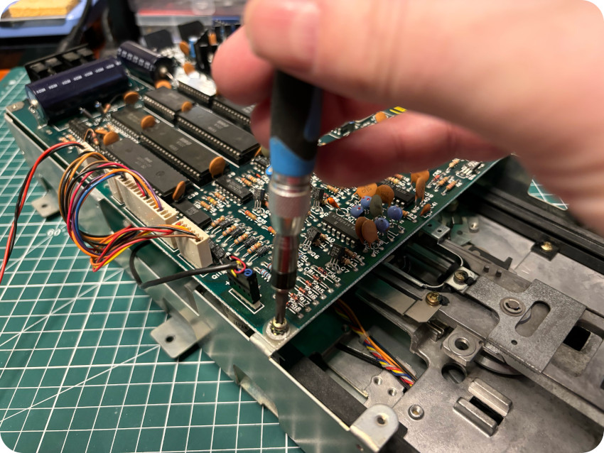
REMOVING PROCEP’S MODS
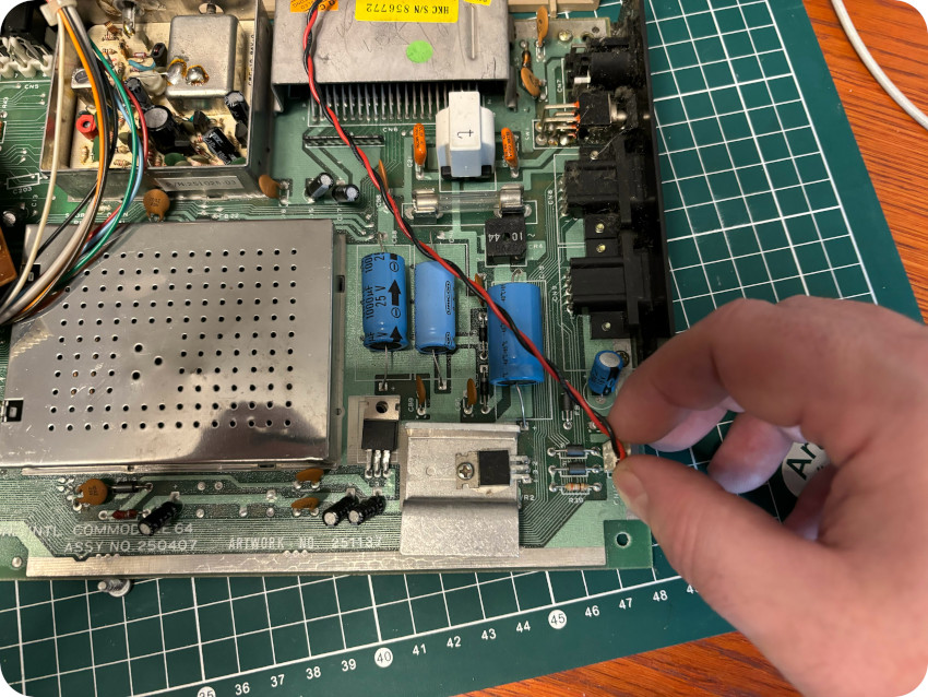
Let’s take a look at the motherboard and PROCEP‘s modifications, starting with the ATV PAL-RVB add-on board, which is soldered on the back on the motherboard.
Here are close-ups of the modifications on the back of the PCB:
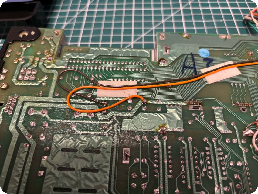
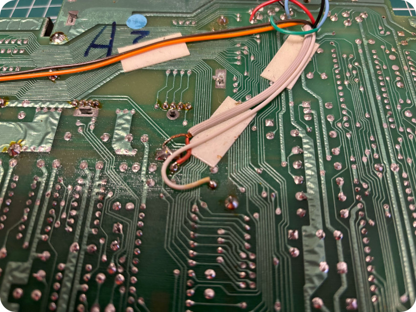
Two traces have been cut for the add-on card to inject RGB signals into the audio-video connector:
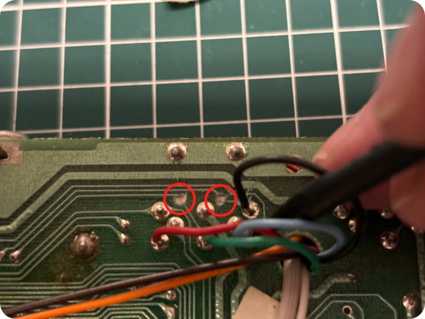
Frankly, by today’s standards (or a least mine), I looks like butcher work. I guess, it was common practices in the days, and PROCEP was probably under pressure from Commodore. But, even if it can be reversed with bodge wires, I hate these kinds of modifications.
Note:
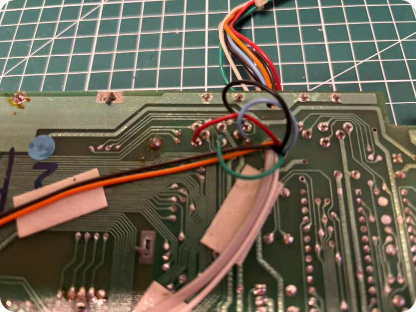
- The PROCEP modifications change the pinout of the audio-video connector to bring R,G,B, CSync signals (as well as +12V) to the AV connector.
- The audio-video connector pinouts (original and modified) are detailed in the “Building an audio-video cable” chapter of this blog post
I proceeded to the removal of the add-on board:
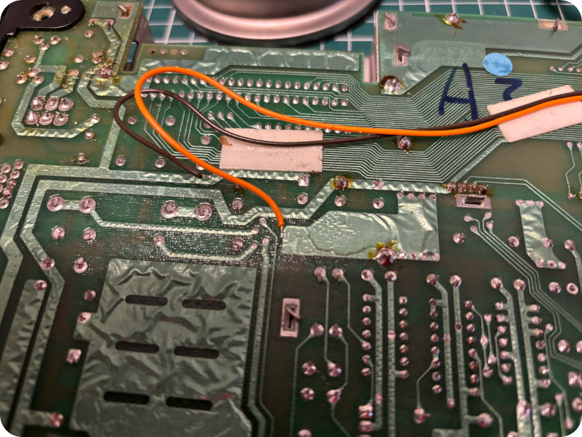
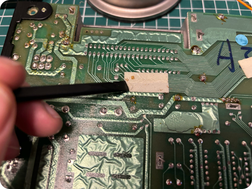
Once done, I checked that I still had continuity on the pins I would need for video composite out, ground and audio:
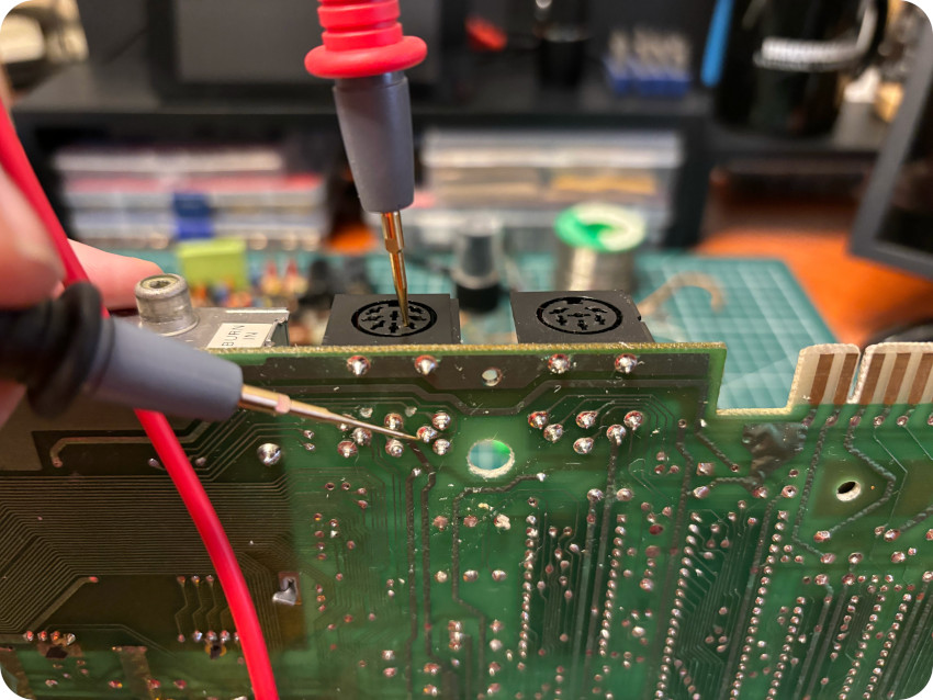
I had continuity for these 3 pins, meaning that even if some traces were cut, this will not affect the composite signal (and that I didn’t have to add bodge wires to fix the cut traces).
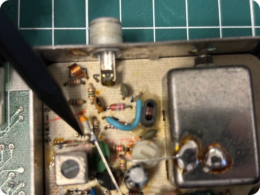
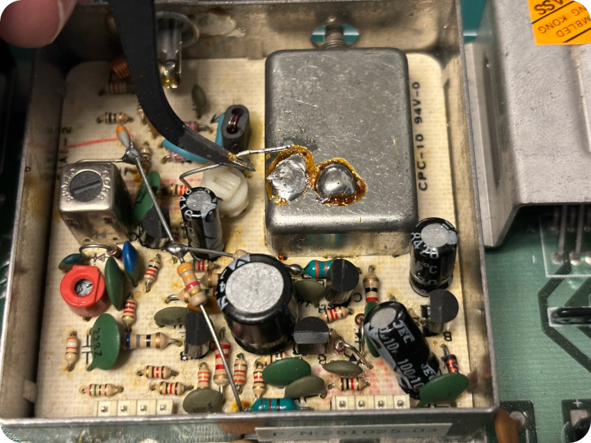
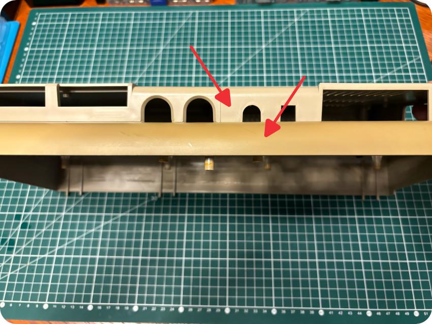
Next, I took care of the RF modulator. Here are the PROCEP modifications:
- A resistor has been grounded
- A 10pF ceramic capacitor has been added and connected to a diode and 2 resistors (3.3kΩ and 33 kΩ)
- A 51 pF capacitor has been removed
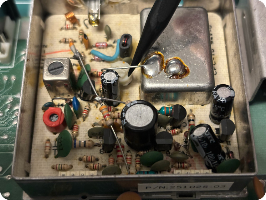
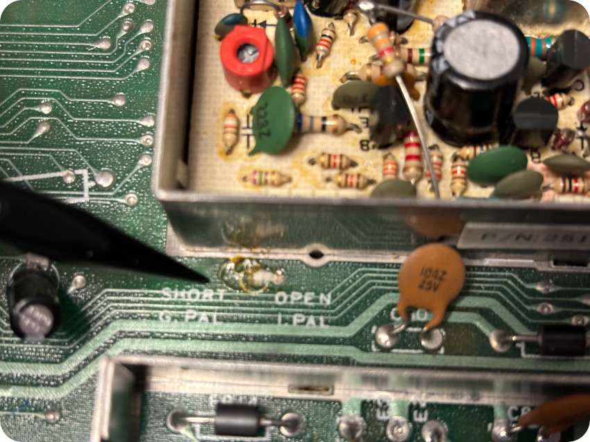
Moreover, a trace (G.PAL / I . PAL) had been cut off. It concerns the frequency of the audio carrier for RF out. I left it this way.
I proceeded to the removal of the modifications done by PROCEP on the RF modulator:
Once done, I visually inspected the board, looking for bad / leaky capacitors. Everything was fine. Then I used my microscope to inspect solder joints:
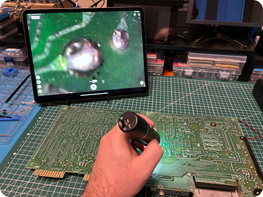
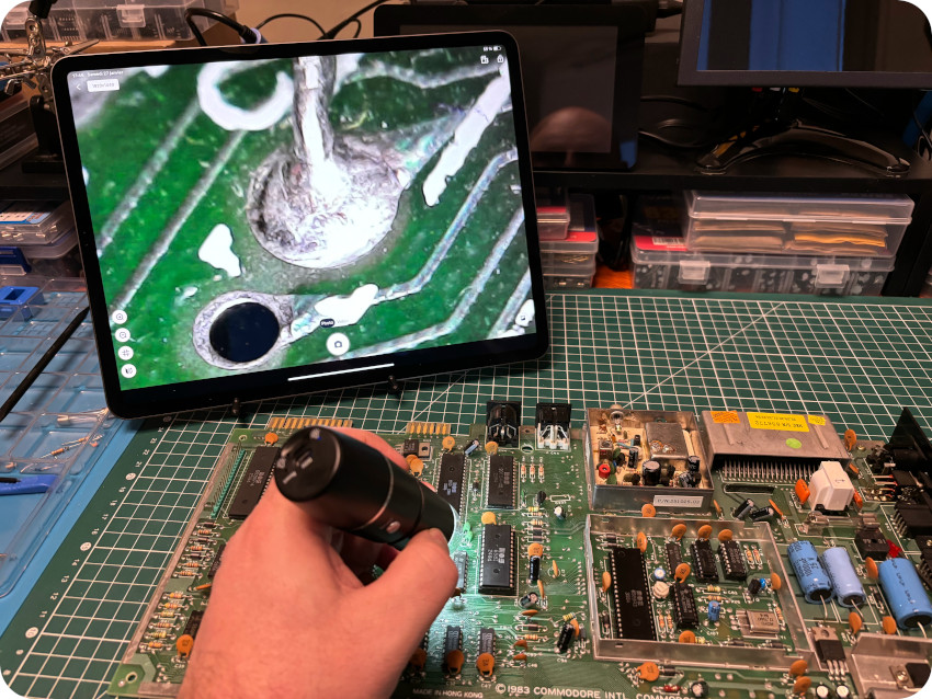
A few of them were mediocre, so I flew fresh solder on those.
Note: for the understanding and removal of the PROCEP modifications, I followed:
- this excellent video: https://www.youtube.com/watch?v=daNWKp5eXBs [French]
- this thread: https://forum.system-cfg.com/viewtopic.php?t=8335 [French]
- this thread: https://forum.system-cfg.com/viewtopic.php?t=12506 [French]
- this thread: https://www.lemon64.com/forum/viewtopic.php?t=76738 [English]
- this thread: https://forum.classic-computing.de/forum/index.php?thread/6165-reparatur-französischer-c64-mit-procep-rgb-platine/ [German]
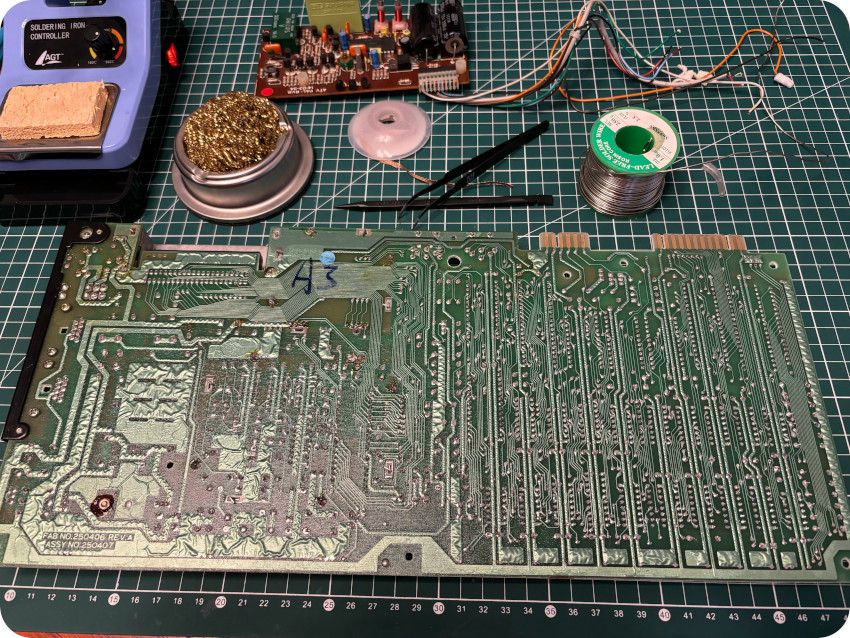
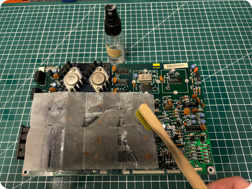
CLEANING THE MOTHERBOARD
It was time to clean the motherboard. I removed dust, especially around the on/off switch, which was filthy:
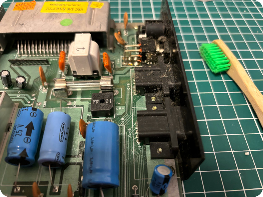
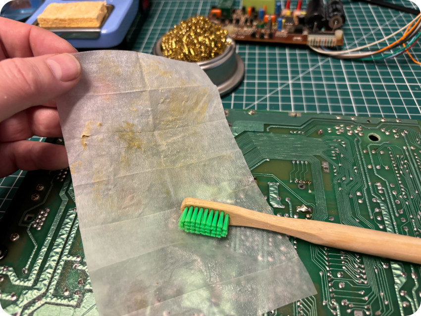
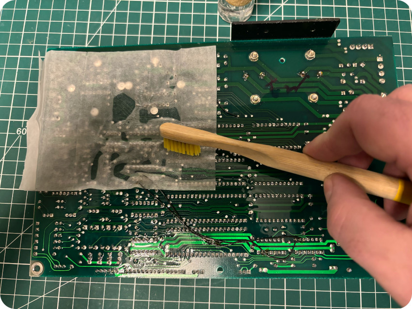
Then I proceeded with my usual process, on both sides of the motherboard: glass cleaning paper towel, soaked in IPA, a tooth brush and a lot of elbow grease:
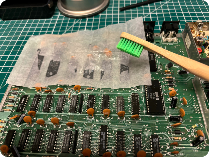
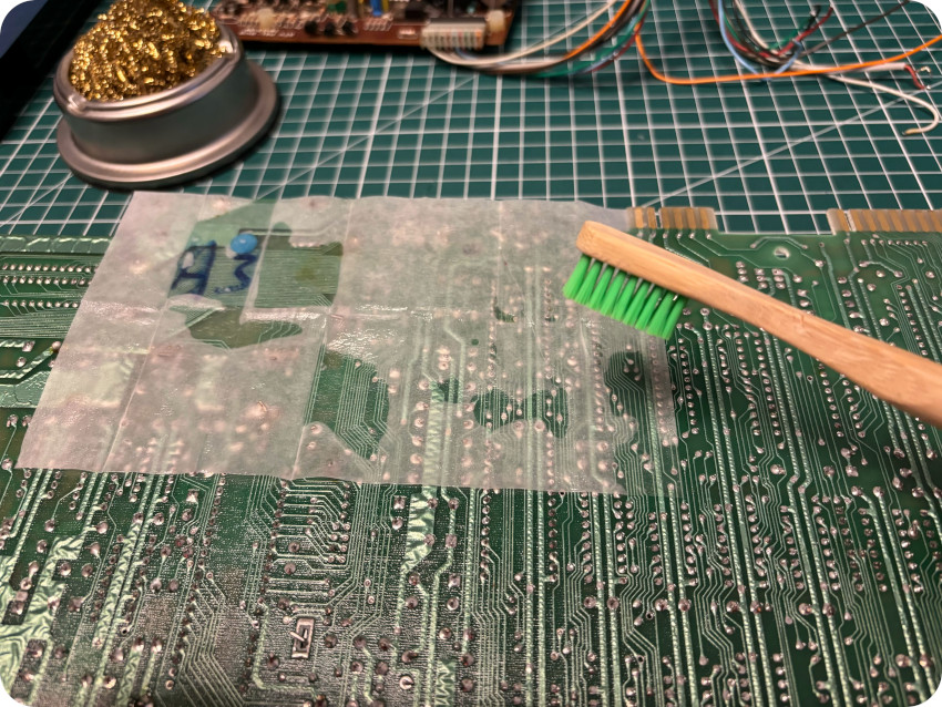
You can see here that these efforts were worthwhile:
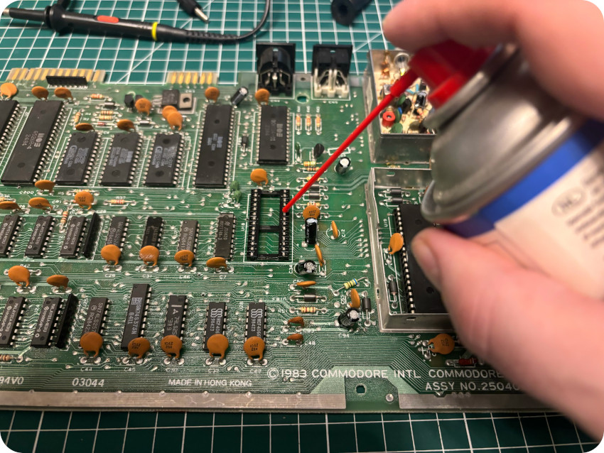
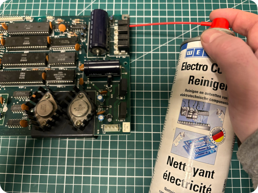
Once cleaned, I sprayed contact cleaner on all connectors:
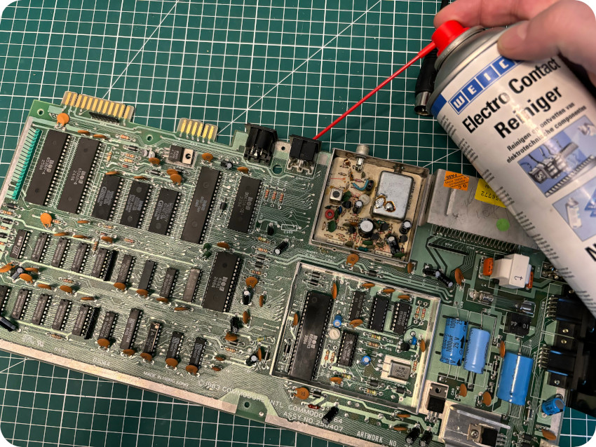
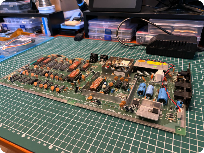
And … there we go !
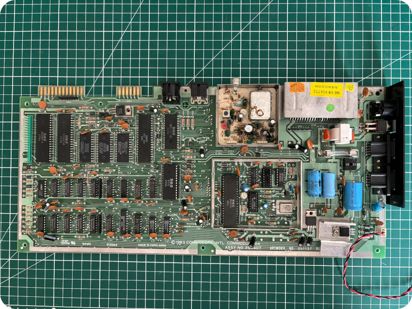
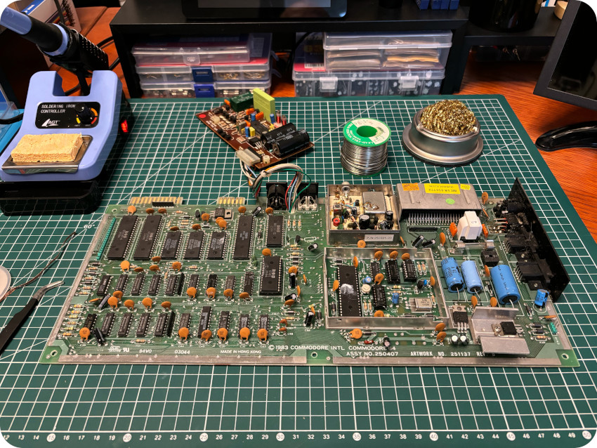
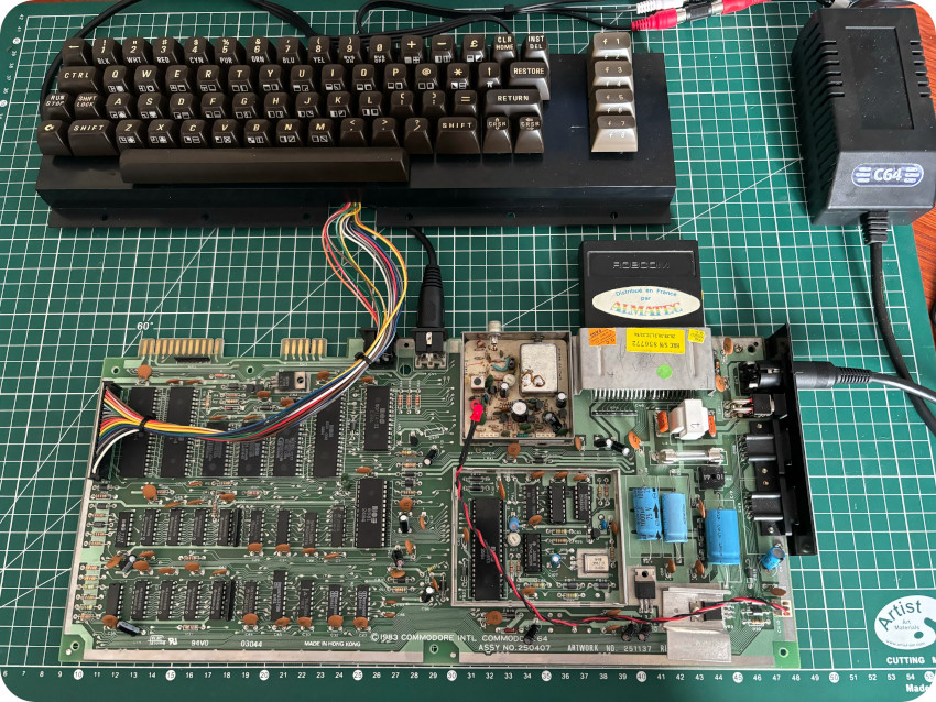
THE PCB (ASSY 250407)
Now that the PCB is clean, let’s take a detail look at the motherboard of my C64. There are many different versions of the C64. Mine is a 250407 revision from 1983, with 1984 components (according to their date codes). Here are the main components for this revision:
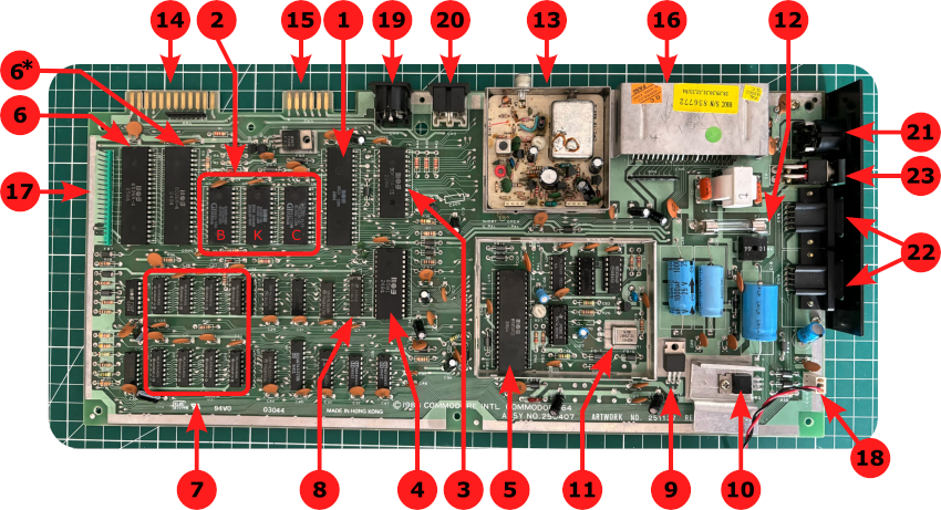
- Microprocessor: The CPU used in the Commodore 64 is a MOS 6510 (a variation of the MOS 6502), clocked at 0.9852484444MHz (PAL region),
- ROMs: the C64 is equipped with 3 ROM chips: the 901226-01 8K BASIC ROM (labelled “B” in the figure, storing the BASIC interpreter), the 901227-03 8K Kernal ROM (labelled “K” in the figure, storing low level OS) and the 901225-01 4K Character ROM (labelled “C” in the figure, storing the character set),
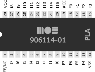
- PLA: the MOS 906114-01 Programmable Logic Array (PLA) is an essential C64 chip, responsible for bank switching and dealing with the chip SELECT signals. It is basically the glue logic that ties everything together. This chip is failure prone, but fortunately, there are now modern replacements for it,
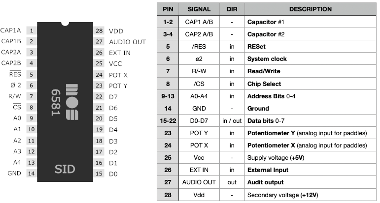
- SID: the MOS 6581 Sound Interface Device (SID) is the C64 built-in programmable sound generator chip. This chip is also failure prone, but there are also modern replacements for it,
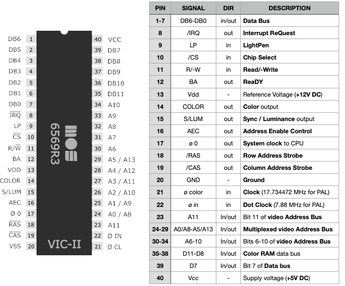
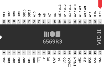
- VIC-II: the MOS 6565R3 (VIC-II, acronym for Video Interface Chip) is responsible for generating video signals, DRAM refresh and clock signal for the CPU. There are different versions and revisions of this chip (6569/8565/8566 for PAL, 6567/6566/8562/8564 for NTSC). Like most of MOS chips, it is also failure prone. Modern replacements for the VIC-II exist too,
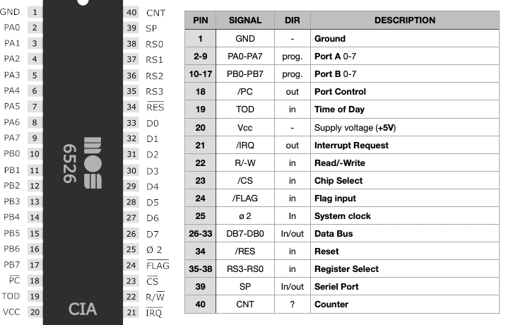
- CIA’s: the MOS 6526 Complex Interface Adapter (CIA) serves as an I/O port controller for the MOS 6502 family of processors (which includes the 6510). it provides parallel and serial I/O capabilities, as well as timers. The C64 includes two identical CIA chips: the first one controls keyboard and joysticks, and the second one controls the serial bus and the user port. MOS CIAs are also failure prone, and there exist a FPGA-based replacement for them,
- RAM: the C64 has 64 kBytes of RAM, here, in the form of 8 x Hitachi HM4864P-3 8kBytes DRAM chips,
- Color RAM: the C64 uses .5kBytes of SRAM (Color RAM), manufactured by National Semiconductor (MM2114N-3),
- 7812 Voltage Regulator (+12V): voltage regulator, powering the SID and VIC-II chips (+12V),
- 7805 Voltage Regulator (+5V): voltage regulator, powering the SID and VIC-II chips (+5V),
- Crystal oscillator: 17.734475 MHz crystal oscillator (PAL),
- Fuse: 3AG 1.5A 32mm quick acting fuse,
- RF modulator: Radio Frequency modulator. The HF signal is used by the PAL version (Europe) in the UHF area (470-862 MHz) on channel 36 (picture carrier on 591.25 MHz),
- User Port: this edge connector is used for external devices such as modems and printers,
- Cassette Port: edge connector used for the datasette. It was also often used as a additional power source for external devices. Nowadays, it is also used for data communication (serial interface, modem, …),
- Cartridge connector: this connector is intended for expansions of the system. It is mainly used for cartridges (games and software, tools, diagnostic cartridges, modems and I/O cards, …),
- Keyboard connector: internal connector for the keyboard,
- Power LED: red power LED,
- IEC Port: DIN-6 serial connector, used as a standard interface for connecting external devices such as disk drives. It is a variant of the parallel IEEE-488/iEC-825 (International Electrotechnical Commission, GPIB/HP-IB) bus. It is not RS232 compatible,
- Audio-Video Port: DIN-8 connector for audio–video. The first C64 models had a 5-PIN jack (like the VIC-20),
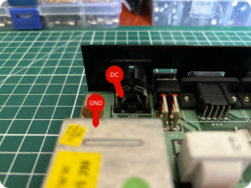
- Power Port: DIN-7 power supply connector (+5 DC / 1.5A and 9V AC / 1.0 A),
- Control Ports: two 9 pin D-SUB male connectors (Atari style) for joysticks, paddles, mouse or lightpen,
- Power on/off: on/off switch.
Note: details of the other components (and other revisions of the motherboard) are available here for example.
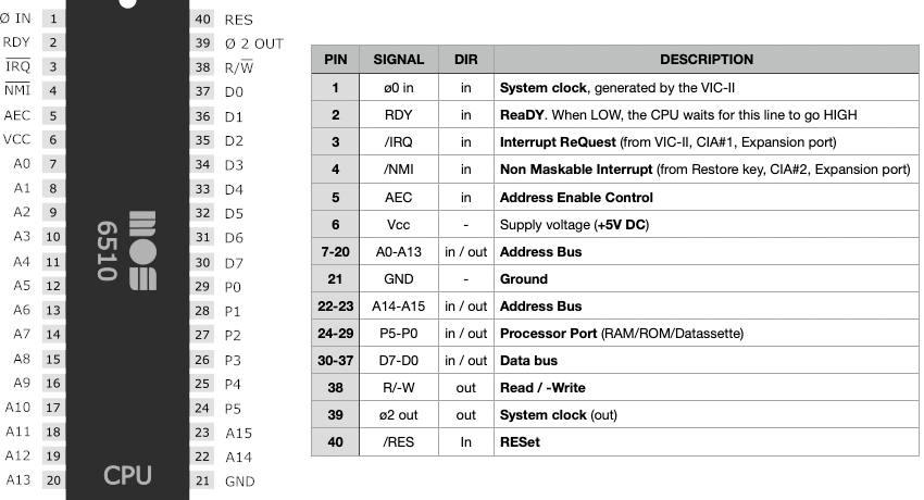
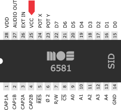
Let’s take a look at the most important components and their pinouts:
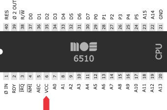
- CPU (MOS 6510) – Source: https://ist.uwaterloo.ca/~schepers/MJK/6510.html
- SID (MOS 6581) – Source: https://ist.uwaterloo.ca/~schepers/MJK/sid.html
- VIC-II (MOS 6569R3) – Source: https://ist.uwaterloo.ca/~schepers/MJK/vic2.html
- CIA (MOS 6526) – Source: https://ist.uwaterloo.ca/~schepers/MJK/cia.html
- PLA (MOS 906114-01) – Source: https://www.c64-wiki.com/wiki/PLA_(C64_chip)
BUILDING AN AUDIO-VIDEO CABLE (COMPOSITE)
Let’s take a look at the audio-video port. Early models of C64 had a DIN-5 port, just like the VIC-20. Shortly after, Commodore built in a 8-pin jack instead of the DIN-5 connector. Mine has a DIN-8 connector.
Note: be aware that are different kinds of 8-pin DIN connectors. For the ones used by the C64, the shape of the arc is like a “shoe horse” (see picture below). The second kind (where the shape of the arc is round) won’t fit into the C64 audio-video connector.
Here is the pinout of the AV cable (source: https://www.c64-wiki.com/wiki/A/V_Jack):
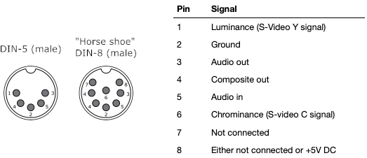
Note:
- pin 8 (+5V DC from PSU) is only connected for later models. For models “ASSY 326298” and “ASSY 250407” (mine), this pin is not connected
- the PROCEP modification changes this pinout: pin 1 → +12V, pin 4 → CSYNC, pin 6 → GREEN, pin 7 → RED, pin 8 → BLUE (“audio” pin 3 and pin 5 being unchanged, as well as pin 2, still GND)
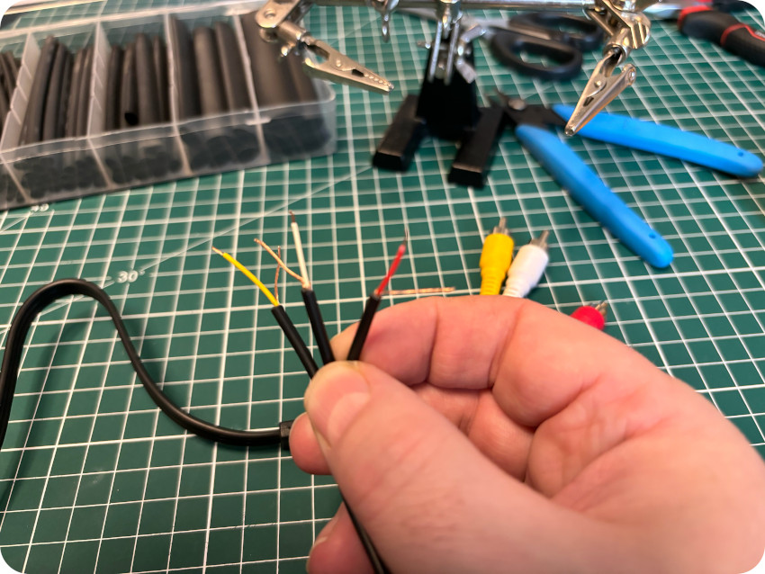
The only cable bundled with the lot I bought that resembled an AV cable was this one:
The “fork” connectors look like old-style TV antenna connectors. Nothing much I could do with this. I needed a composite AV cable for my own purposes.
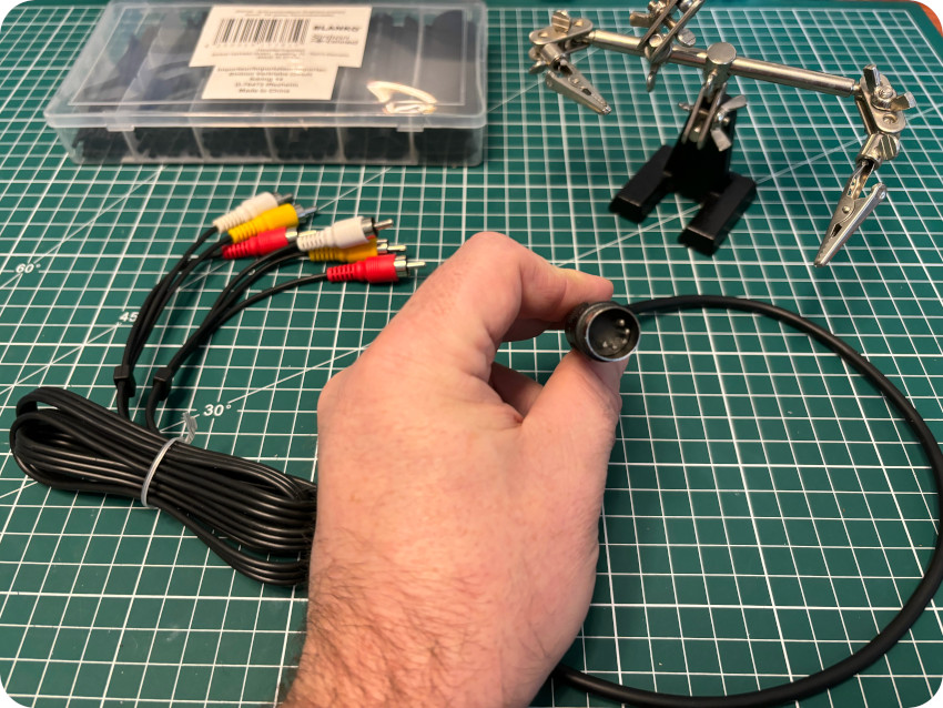
Fortunately, I already had in stock:
- a (new) audio-video cable with RCA connectors for composite signal (yellow plug) + stereo audio signals (red and white plugs)
- a (half) DIN-5 cable (the other half was used for my Apple IIc null modem cable)
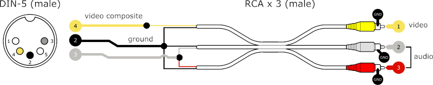
So, I decided to build an AV (composite) cable for my C64 from these cables. The wiring is simple, since only three pins are needed from the DIN-5 side:
- pin 4: composite
- pin 3: audio
- pin 2: ground
On the “RCA” side:
- The composite video signal (inner pin from yellow connector) is connected to video out (pin 4)
- All grounds (collars from audio left, audio right and video connectors) are connected together (to pin 3)
- Left and right audio signals (inner pins from red and white connectors) are connected together to mono audio out (pin 2)
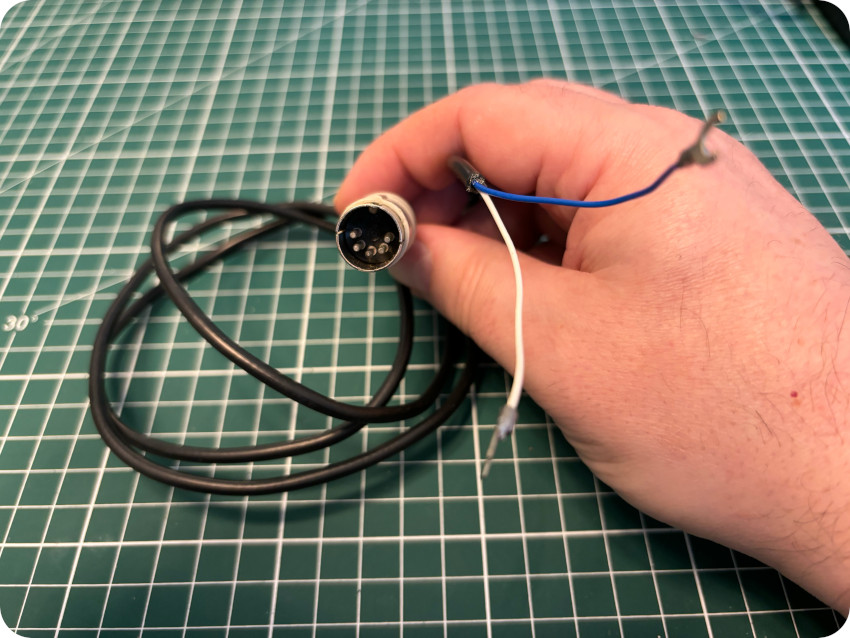
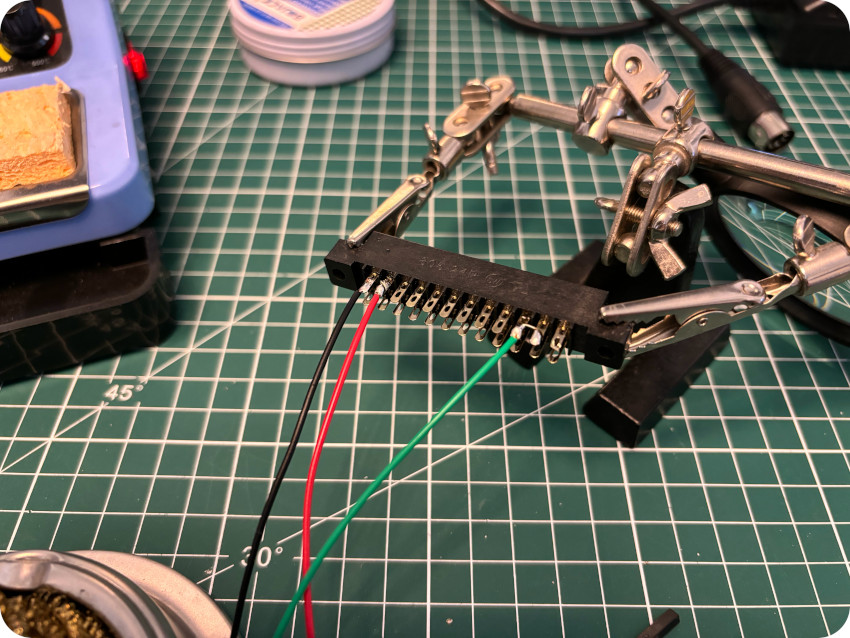
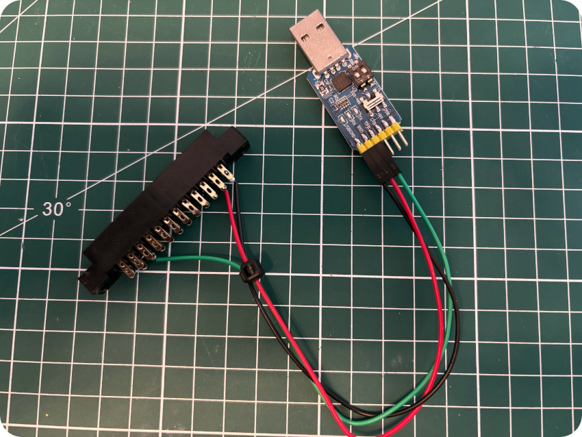
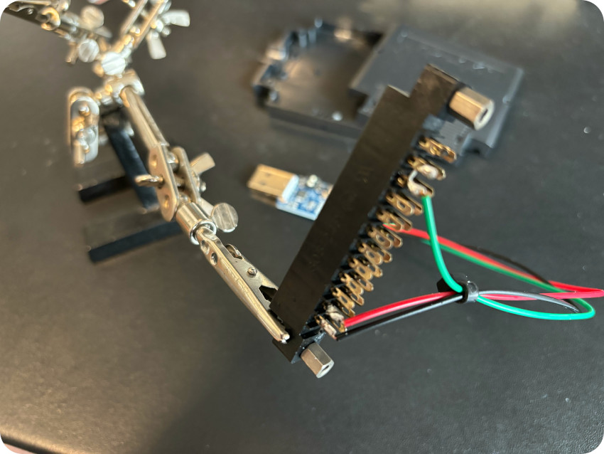
Let’s start the build process, stripping wires 2, 3 and 4 and cutting off the other ones on the DIN-5 side,
I cut the audio-video RCA cable in two, then stripped the wires and bundled together the grounds:
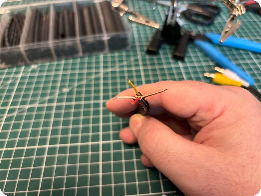
Then :
- I soldered the grounds (copper wires) together (ground pin 2 on DIN-5 side)
- I bundled red and white wires together (RCA side), then soldered them to the audio black wire (audio pin 3 on DIN-5 side)
- I soldered to yellow wire (RCA side) to the video white wire (video pin 4 on DIN-5 side)
- I protected the connections with heat shrink tubes
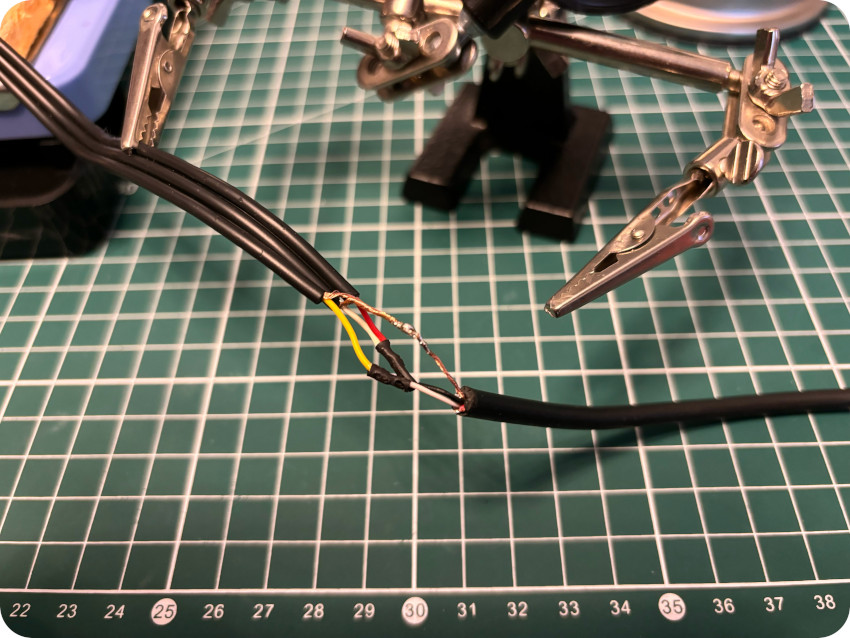
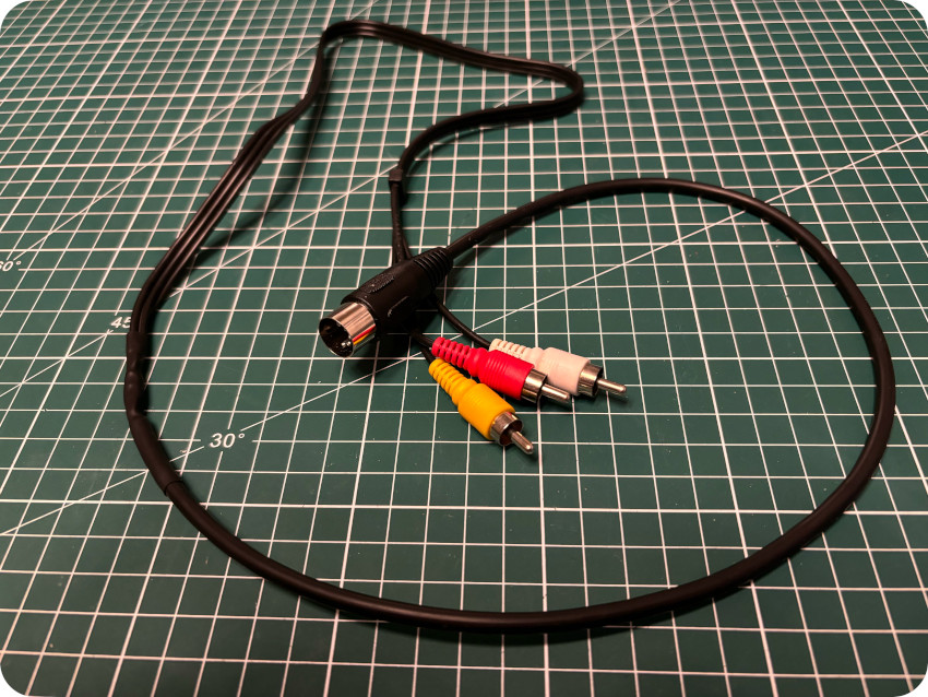
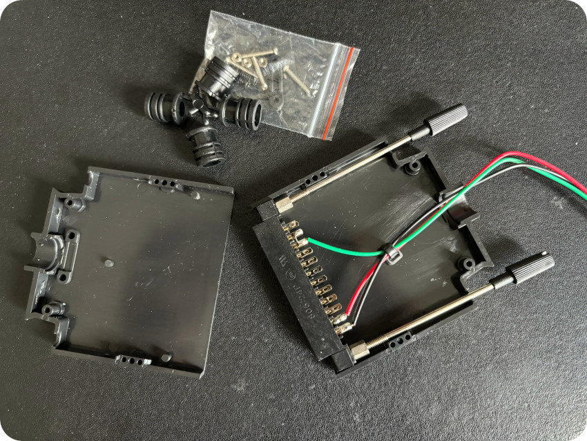
Here is the final result:
FIRST RUN (AND FAIL)
The brand new PSU had arrived from Poland, the PROCEP mod was removed, the motherboard was inspected & cleaned, and a new AV cable was built. It was about time for a first run !
- I connected the AV cable to the C64 and to my small composite LCD screen
- I plugged in the new PSU
- I turned on the C64
- The red power LED went on !
- … and nothing on the screen.
No signal at all (not even a black screen):
Hummm, this is NOT a good start !
Let’s try the most obvious checks.
First, I checked if there were chips that were getting too hot. A high temperature is often a sign a dead or faulty component. I don’t have any particular equipment for measuring temperature … so I simply used my finger. The CPU, PLA, SID and the VIC-II were getting warm. At least, there were signs of life ! The VIC-II is the hotter one, but that is usual. The least warm was the CPU. The RAM chips were total cold.
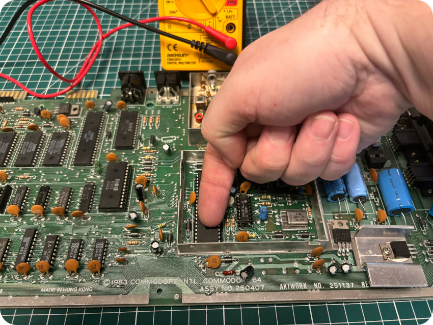
A few components are socketed (SID, VIC-II, …). I carefully pulled them off from their sockets, sprayed contact cleaner, then re-seated them:
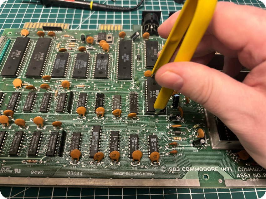
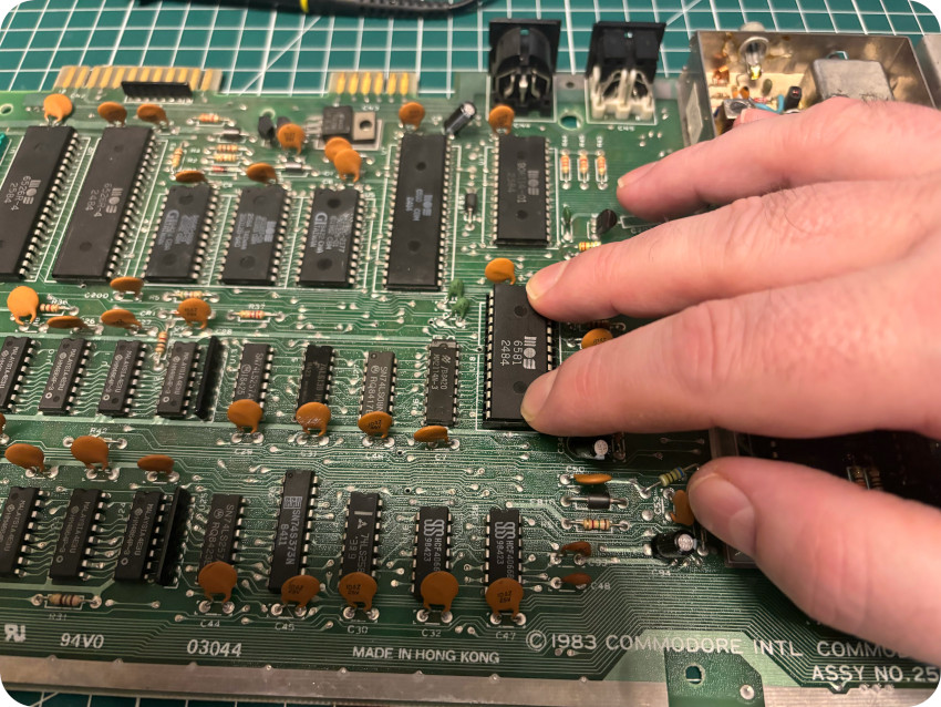
A couple of them were a bit oxidized, so I cleaned their legs with a fiberglass pen before putting them back in their sockets:
I turned the power back on. Still absolutely nothing …
ANALYSIS
At this stage, here are the most probable root causes:
- Bad PSU: this can be ruled out. The PSU is brand new (and I checked that outputs were fine)
- Bad voltages: to be checked first
- Bad / dead fuse: this can be ruled out (checked)
- Bad crystal oscillator: to be checked
- Bad / dead VIC-II: this is my main suspect. It provides video signal, but also provides the clock signal to other components. Like most of MOS chips, it is prone to failure. See here for tips / fault guide: https://www.pictorial64.com/tips/vic.html
- Bad / dead PLA: this could also be a suspect, and, like the VIC-II, it is prone to failure. Most common symptoms include a black screen, or flashing colored startup screen characters. I have no video signal at all. See here for tips / fault guide: https://www.pictorial64.com/tips/pla.html
- Bad / dead CPU: of course, the CPU itself could be faulty,
- Bad / dead RAM: bad RAM chip are no uncommon, especially those from Micron Technology (with “MT” letters printed on). Mine were manufactured by Hitachi and are less prone to failure. Nevertheless, RAM chips are among the first to fry in case of over-voltage, resulting in a black screen. Here, I have no signal at all. See here for tips / fault guide: https://www.pictorial64.com/tips/ram.html
- Bad video cable: of course, I may have screwed up when building the video cable,
- Damages linked to the PROCEP modification: lack of video signal could be the sign of damages links to the PROCEP mod (or damages when I removed it)
Of course, this could be a combination of all these … over even something completely different. Since it could take some time, I ordered in case I’d need to replace them:
- A refurbished (but tested as working) VIC-II (6569R3) – on LeBonCoin
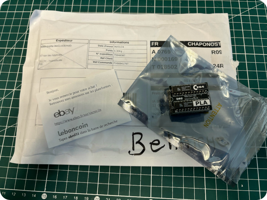
- A brand new PLA recreation – on eBay
Note: this was my first purchase on eBay, and it went very well. I received the PLA very, very quickly. It was very well packed. The vendor is a retro-computer enthusiast, extremely nice. I recommend him warmly !
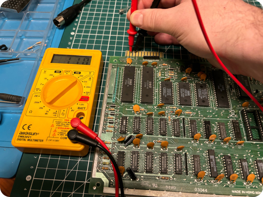
VOLTAGES
For now, let’s test the main voltages:
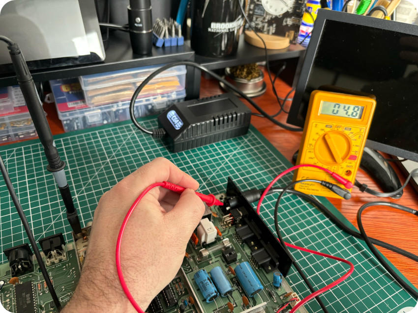
- PSU voltages (DC): measure gives +4.8V which is good (should be close to +5V)
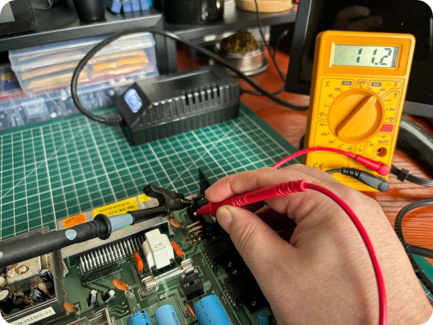
- PSU voltages (AC): measure gives 11.2V which is good (should be between 9.5 and 12V AC)
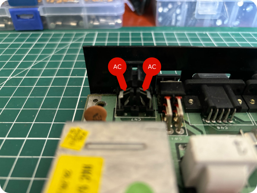
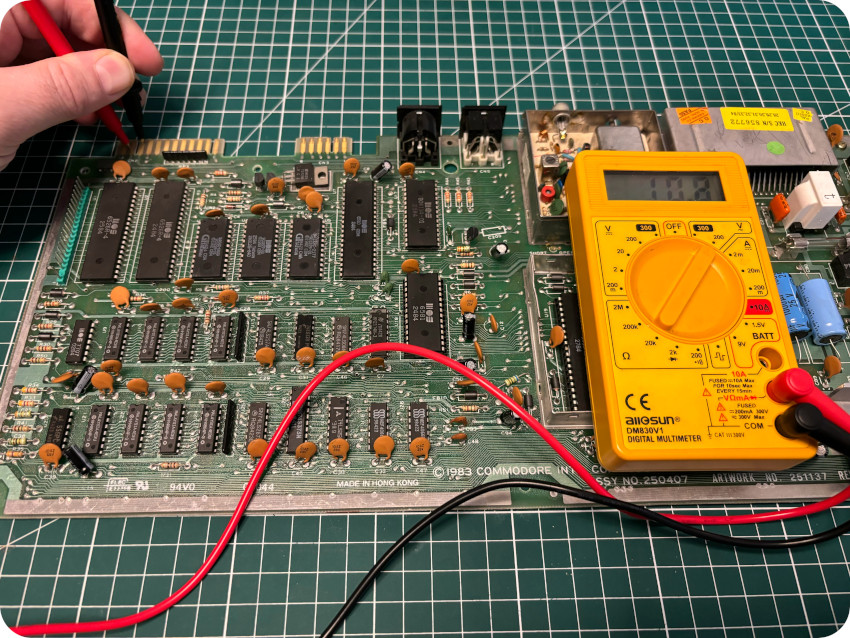
- User Port (AC): voltage can be tested via the User Port, as pictured here (between pins 10 and 11):
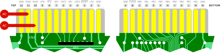
I measured 11V AC, which is a bit too high (should be around 9-10 V AC):
I checked a couple of time, and after a while, measured … 0V. It turned out the fuse had just blown:
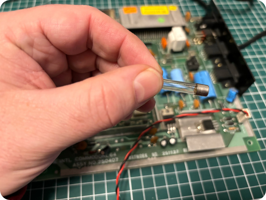
Not a good sign. But at this point, not much I could do but replacing it, and trying to find why it blew. I could easily find a proper replacement (though a few mm shorter than the original one):
With a fuse back on, I measured voltages between pins 11 and 10 on the User Port, and found 10.8V AC, still a bit high :
- User Port (DC): DC voltage can be tested as pictured here (between pins 1 and 2 of the User Port):
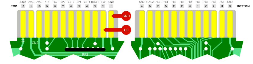
I measured +4.8V DC, which is good:
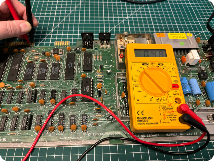
- Datasette Port (DC): DC voltage can be tested on the Datasette Port as well (between pins 1 and 2):
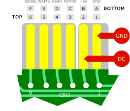
I measured +4.8V DC, which is also good:
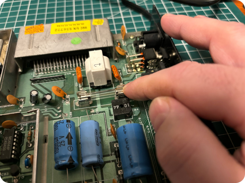
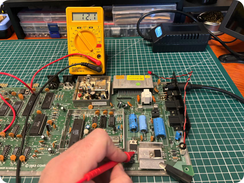
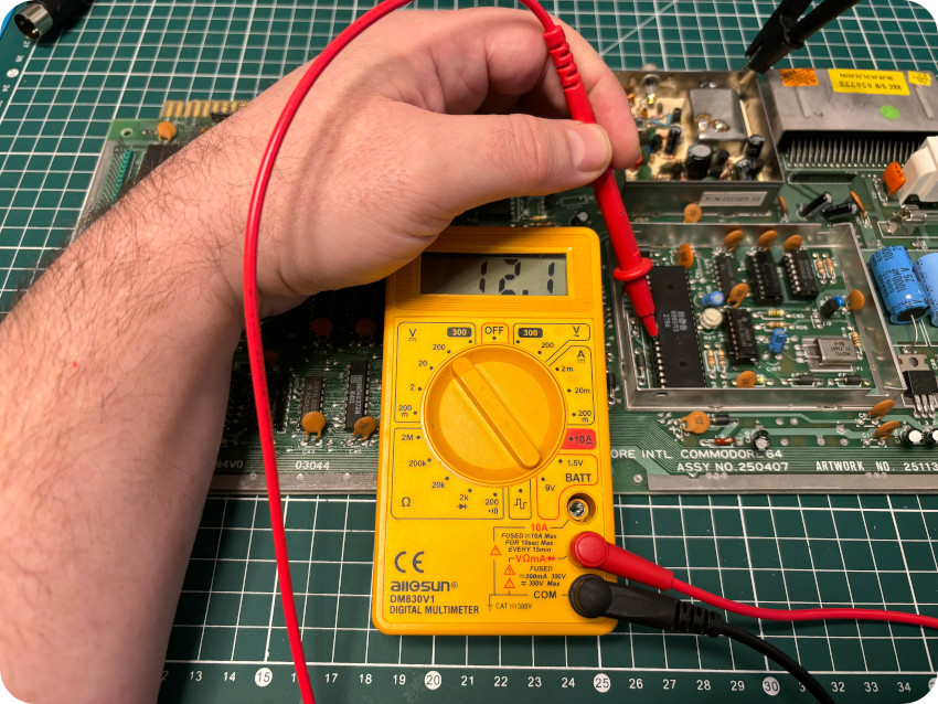
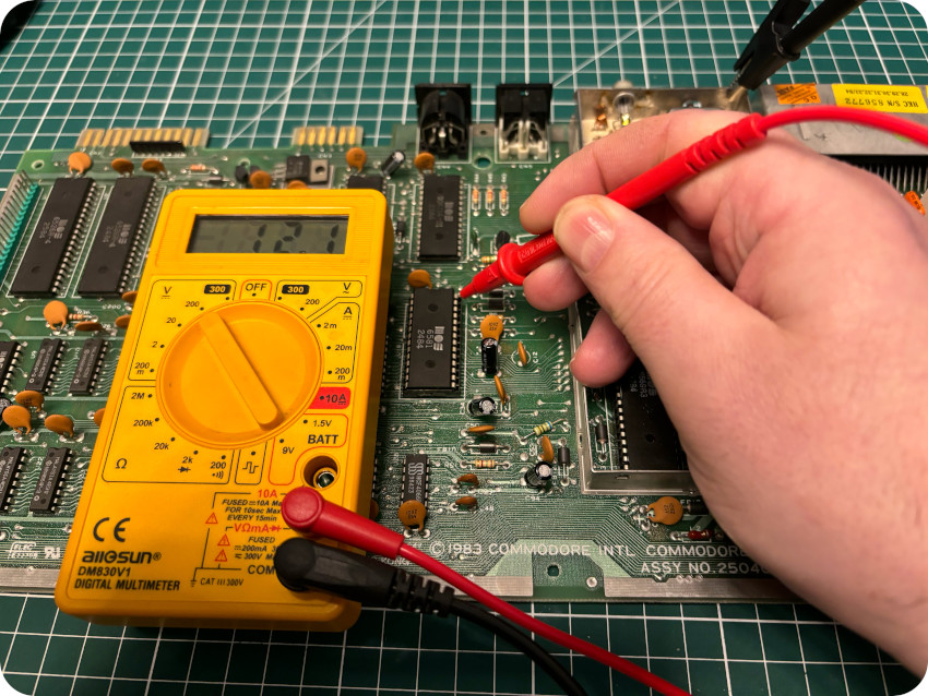
- Voltage Regulator (12V): I measured +12.1V DC out (+22.3V DC in), which is good:
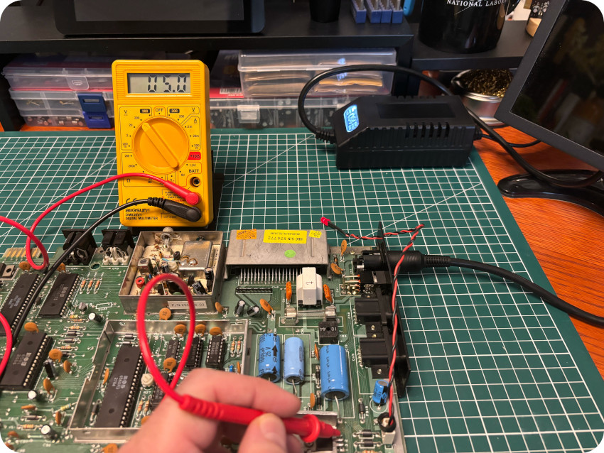
- Voltage Regulator (5V): I measured +5.0V DC, which is perfect (+11.2V in):
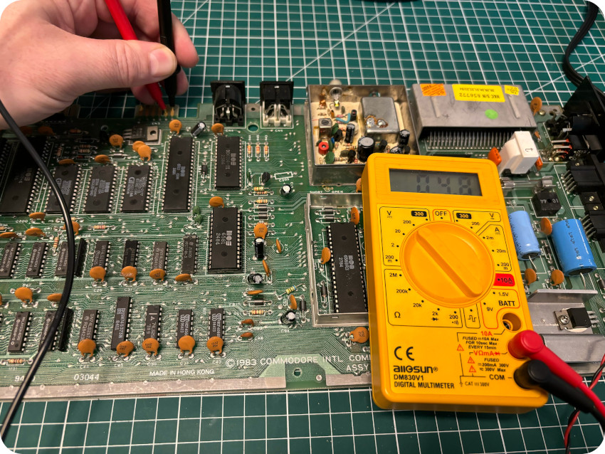
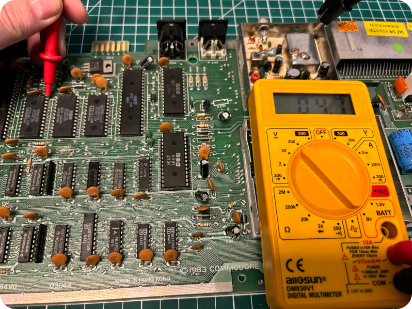
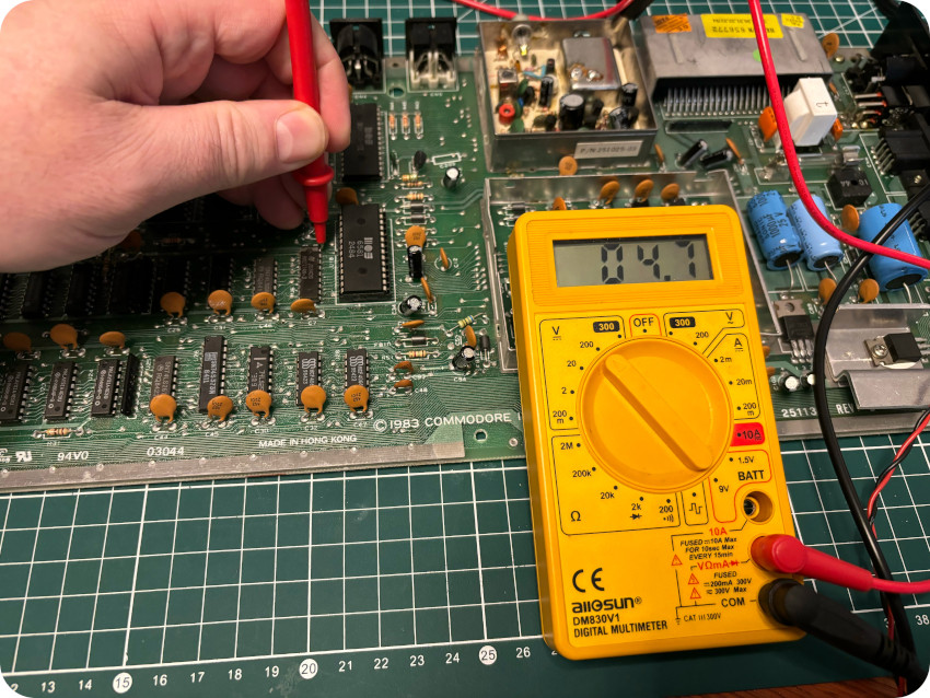
- CPU: I checked the voltage on pin 6 and measured +4.7V DC, which is good:
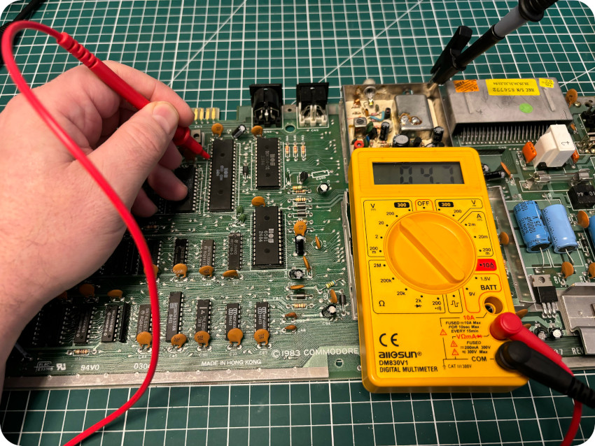
- PLA: I checked the voltage on pin 28 and measured +4.8V DC, which is good:
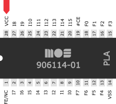
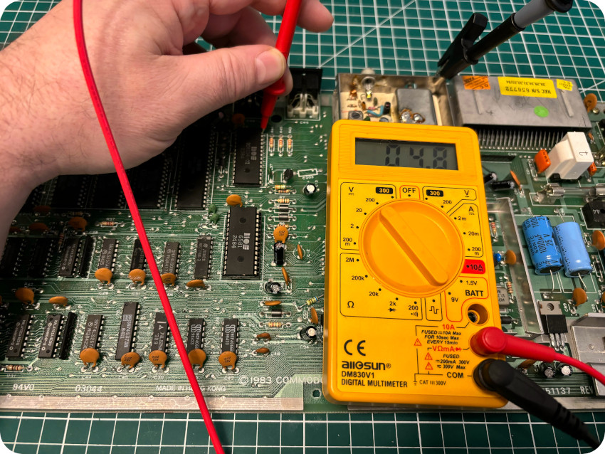
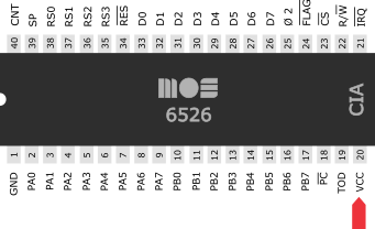
- CIA‘s: I checked voltages on of both CIA‘s (pin 20), and found +4.8V DC (for both), which is good:
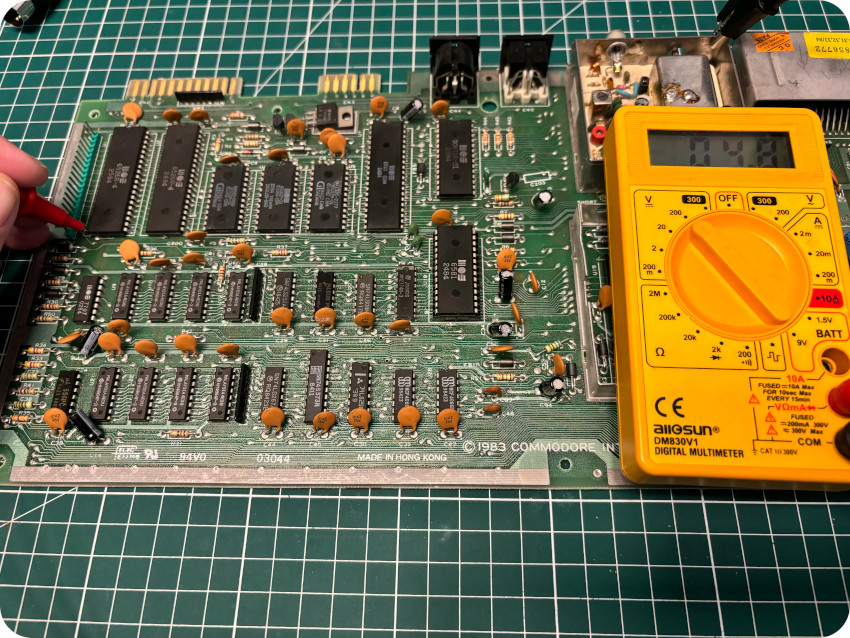
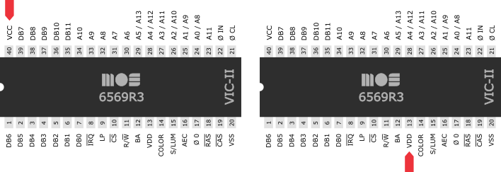
- VIC-II (+5V, +12V): I checked voltages on the VIC-II (+5V, pin 40 and +12V pin 13), and measured +5.0V DC and +12.1V DC, which are both good:
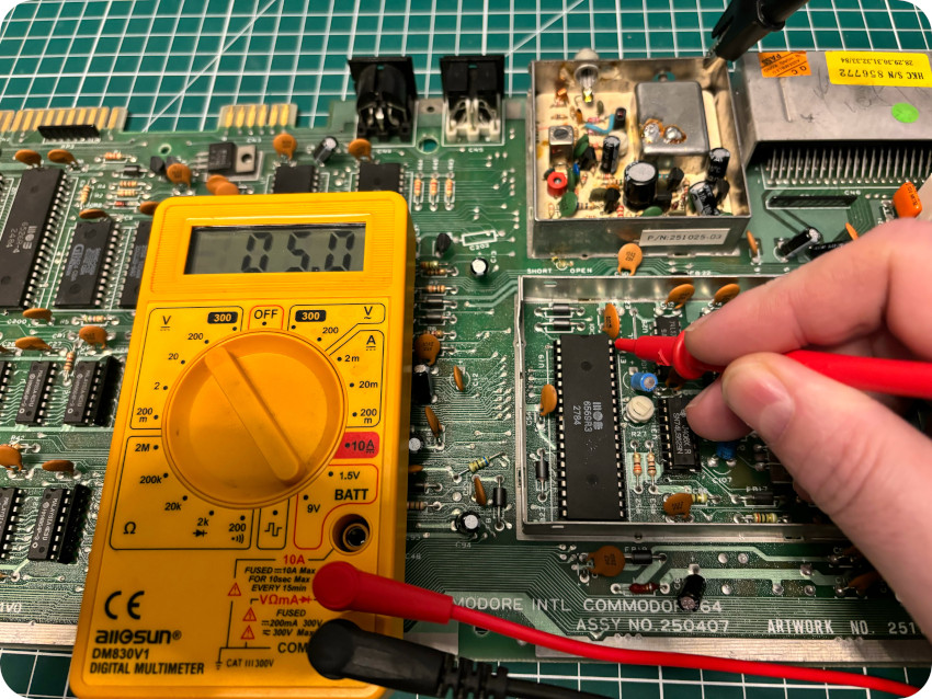
- SID (+12V): for the SID chip, I checked pin 25 and measured +12.1V DC, which is fine:
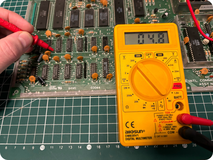
- ROMs:I checked the 3 ROM chips (pin 25) and measured +4.7V DC, which is good:
- RAM chips and Color RAM: finally, I check all RAM chips and the Color RAM, and found good voltages as well:
At this point, everything looks fine (apart from AC voltage a bit too high on the User Port). And no clue yet on why the fuse blew. My gut feeling is that one of the major components (VIC-II, PLA, CPU, …) is misbehaving.
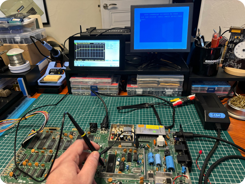
SIGNALS
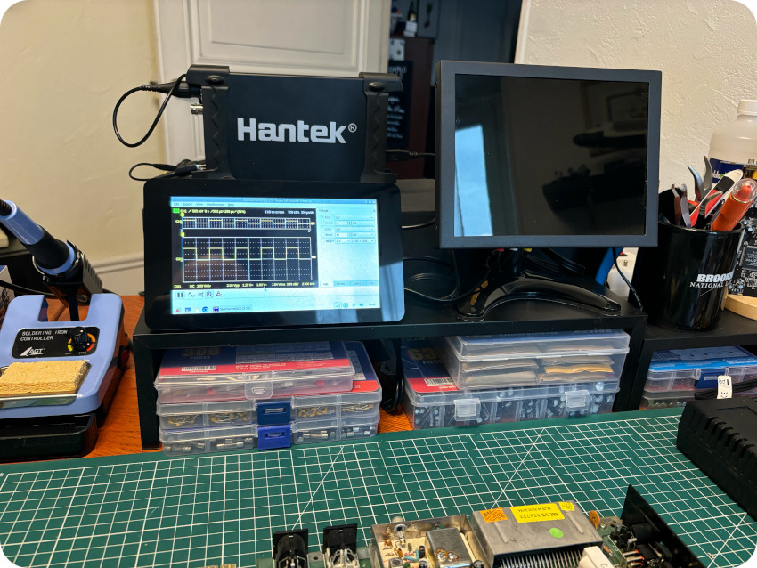
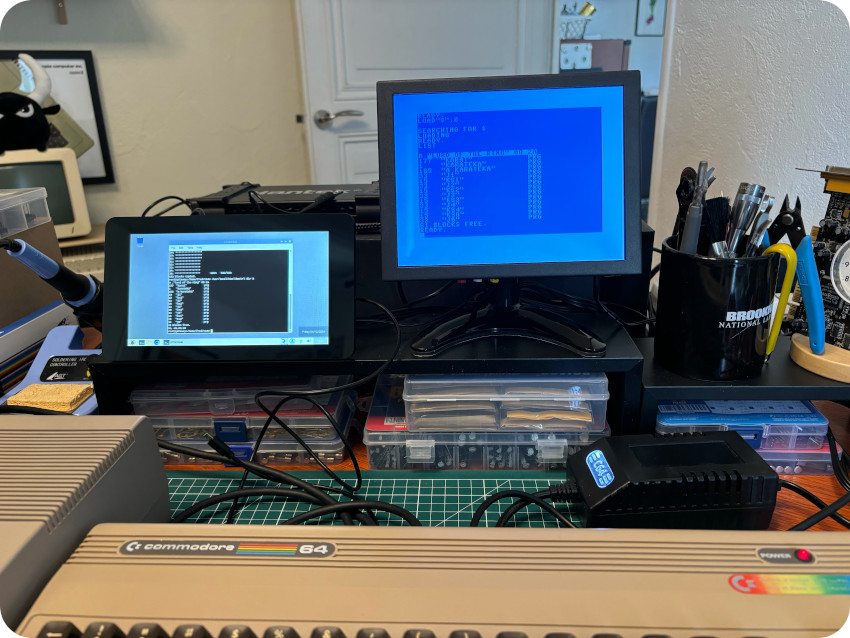
To go further, I needed to visualize signals. Fortunately, my lovely wife had gifted me a Digital Oscilloscope for Christmas ! It is a Hantek 6022BE, a two channels 20 MHz Digital Oscilloscope. It is not a high performance oscilloscope, but it perfectly suit my needs for old school computers. At the software level, I did not use Hantek’s proprietary software, but the open source OpenHantek6022 project, available here: https://github.com/OpenHantek/OpenHantek602
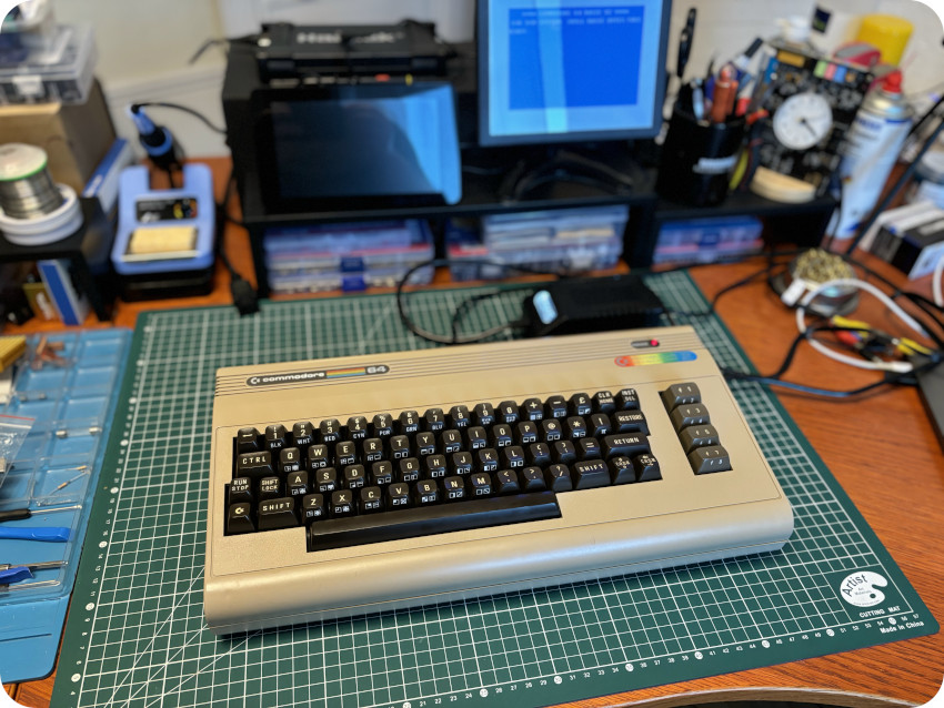
It is much better than the proprietary MS Windows-only one, an runs well on MacOS and GNU/Linux (including my trusty all-purpose Raspberry Pi that now seats on my redesigned workbench):
Note: bear in mind that I haven’t used an oscilloscope since the time I was a particle physicists, 25 years ago. I am really rusty and may have done mistakes or said stupid things in the following part.
First, let’s take a look at the CPU:
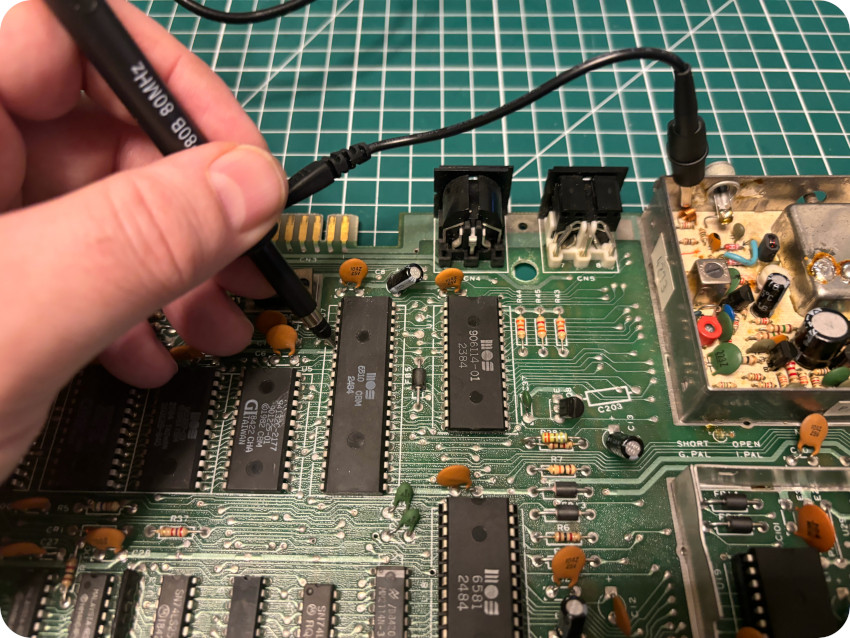
- CPU – pin 6 (VCC) – Let’s see I the CPU is still powered (+5V):
It looks good, so let’s move on and see what the CPU is doing.
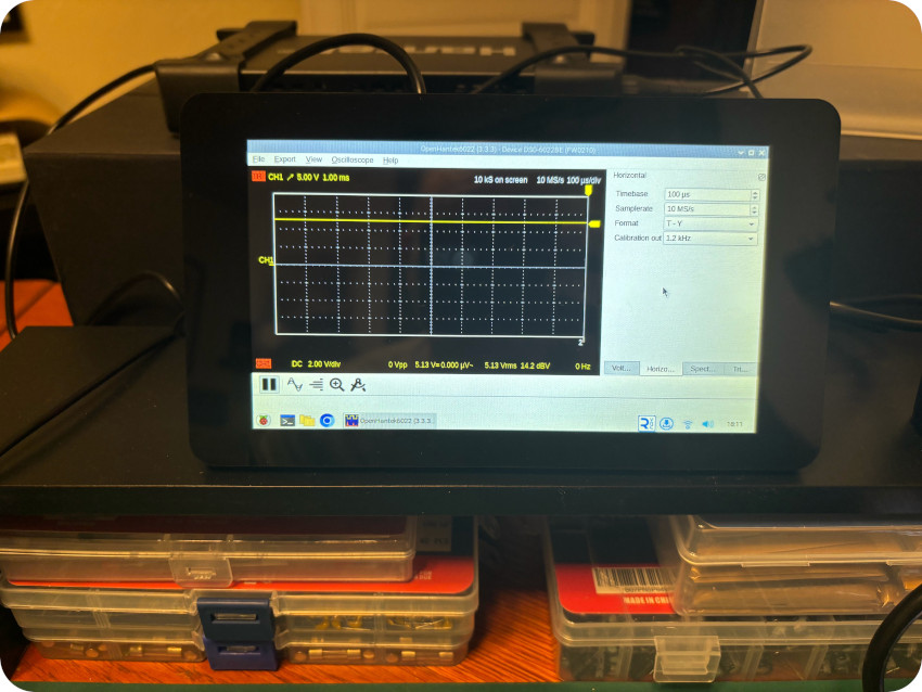
- CPU – pin 37 (D0) – Is there is any activity on the data bus ?
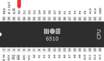
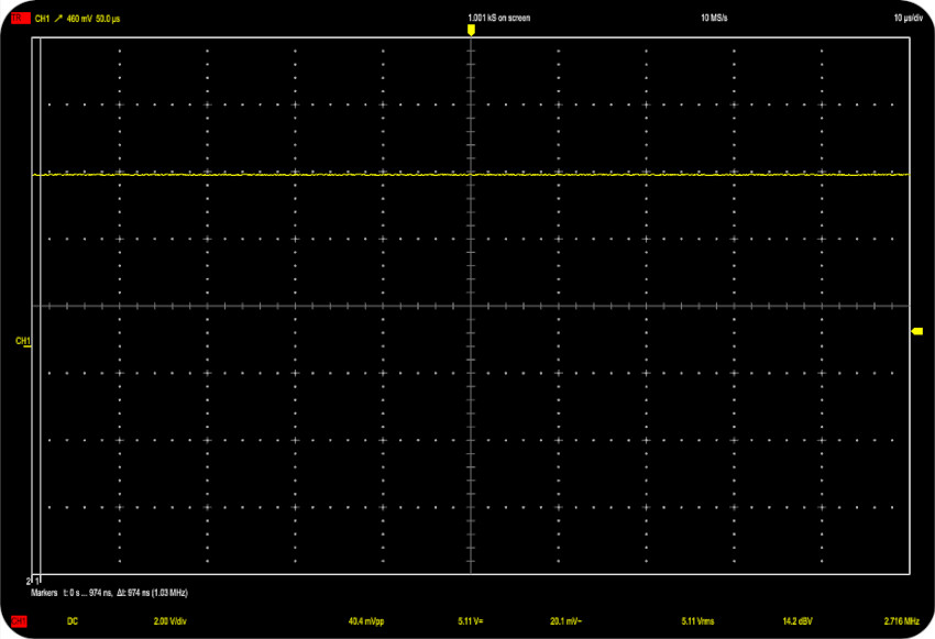
No activity whatsoever. The signal is stuck high. This looks bad. Is the CPU dead ?
- CPU – pin 1 (φ in) – Let’s take a look at the clock signal (provided to the CPU by the VIC-II):
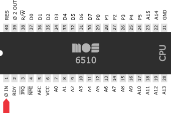
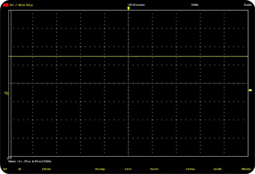
And. … there is no clock signal. This would explain why there is no activity on the data bus since the CPU needs the clock signal to work properly.
For now, we still don’t know whether the CPU is dead or not. What we know so far is that the CPU is not fed with the system clock it needs.
The clock signal is provided by the VIC-II (pin 17), so let’s take a look at it !
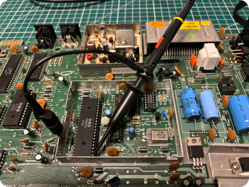
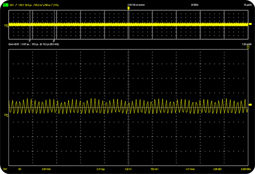
- VIC-II – pin 17 (system clock) – Let’s see if the VIC-II outputs a system clock:
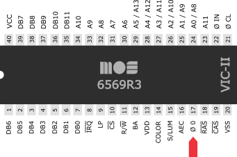
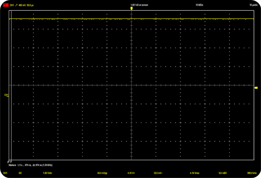
It does not. It was a bit expected, since there was clock signal at the CPU level.
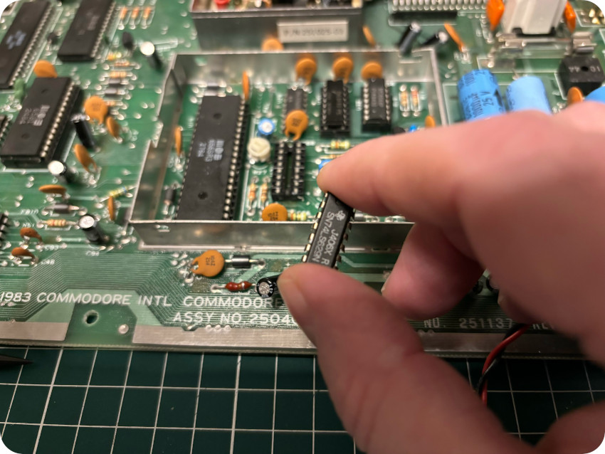
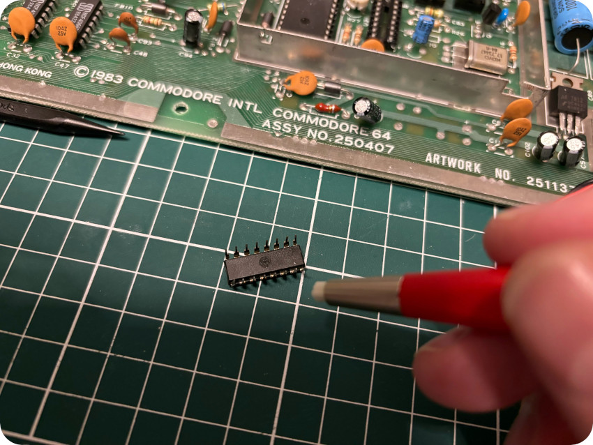
The clock circuit (see diagram below) generates the clock “φ Color” (needed for color bursts) from the Crystal Oscillator (Y1) and then creates a downscaled “Dot Clock“. Four IC’s are involved here: a voltage controlled oscillator 74LS629N (U31), a 4-bit counter 74LS193 (U30), a phase-frequency detector MC4044 (U32) and a dual Flip-Flop 74LS74 (U29):
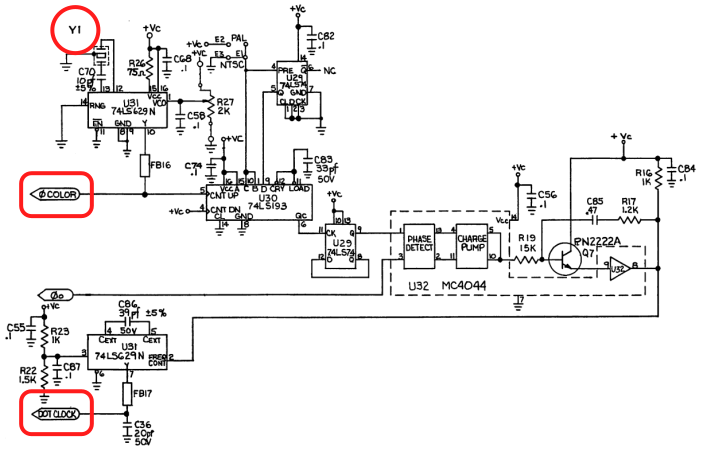
In the end, the clock circuit, based on the 17.734475 MHz (for PAL) signal from the oscillator:
- creates a 17.734475MHz (PAL) “φ Color” signal, fed to the VIC-II (pin 21)
- multiplies this clock by 4/9 to create the 7.892MHz (PAL) “Dot Clock“, fed to the VIC-II (pin 22)
Let’s take a look at these two signals !
- VIC-II – pin 21 (φ color) – We should see the input from the clock circuit:
And … it looks OK !
- VIC-II – pin 22 (φ in) – We should also see the signal fed in by the clock circuit:
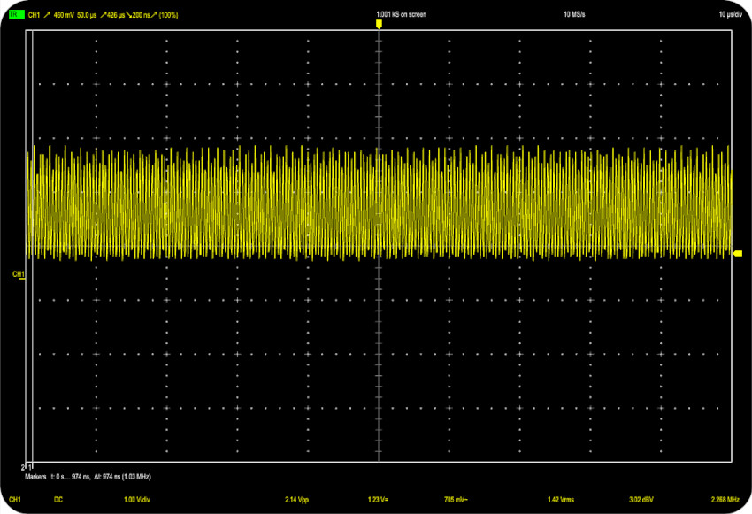
And … it looks OK too !
So far, we know that:
- the clock circuit it working
- there is no clock signal out of the VIC-II
- there is therefore no clock signal fed to the CPU (and thus no activity on the data bus)
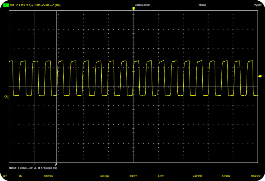
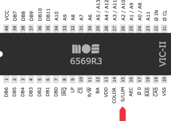
Let’s now check if there is any video signal out of the VIC-II – from either pin 14 (Color) or pin 15 (Sync / Luminance).
- VIC-II – pin 14 (color) – Let’s take a look at the video signals, starting with the color signal (pin 14):
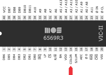
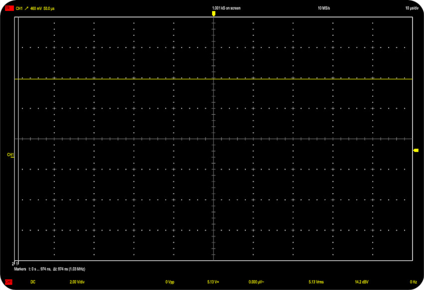
And … I got a flat signal. Same for pin 15 (Sync/Luminance).
Let’s summarize what we know so far:
- The clock circuit works
- If feeds the VIC-II with proper clock signals (“φ in” and “φ color”)
- The VIC-II doesn’t output any system clock, therefore there is no CPU activity
- The VIC-II doesn’t output any video signal
Houston, we have a problem with this VIC-II !
REPLACING THE VIC-II
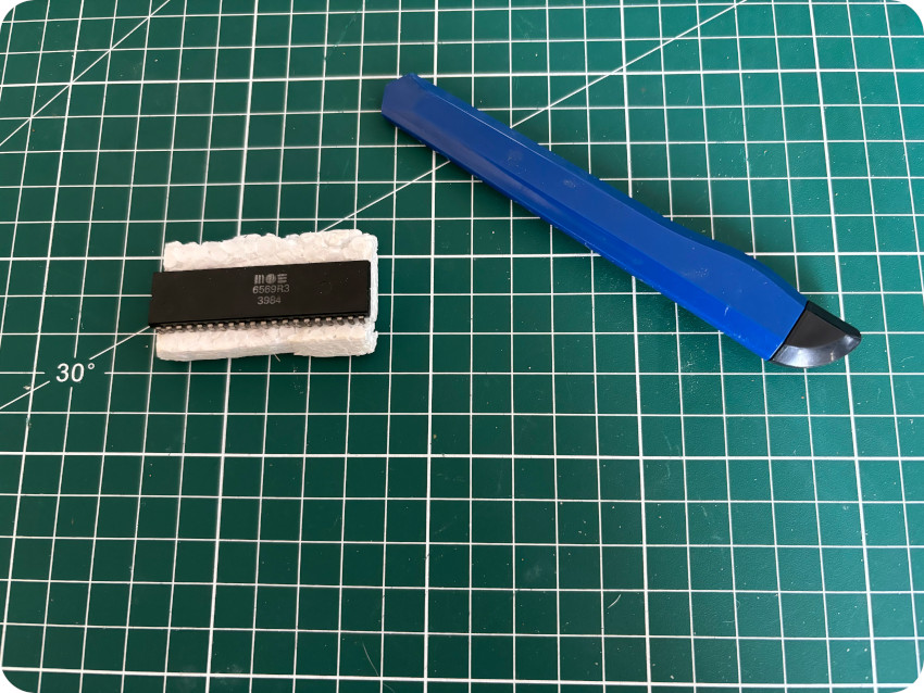
Fortunately, the VIC-II I bought online (on LeBonCoin) had arrived. It was … not very well packed: no ESD bag nor ESD foam. But it was intact and it was said to have been tested OK:
I removed the old VIC-II and plugged in the new one. I power up the C64 and ran these tests:
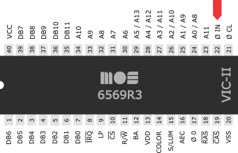
- VIC-II (pin 17) – Does the new VIC-II output a system clock (to the CPU) ?
Yes it does ! Nice !
- CPU (pin 1) – Does the CPU have a system clock (from the VIC-II) ?
Yes it does ! Awesome !
- CPU (pin 37) – Is there activity on the data bus ?
Yes there is ! Looks promising !
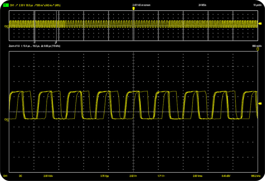
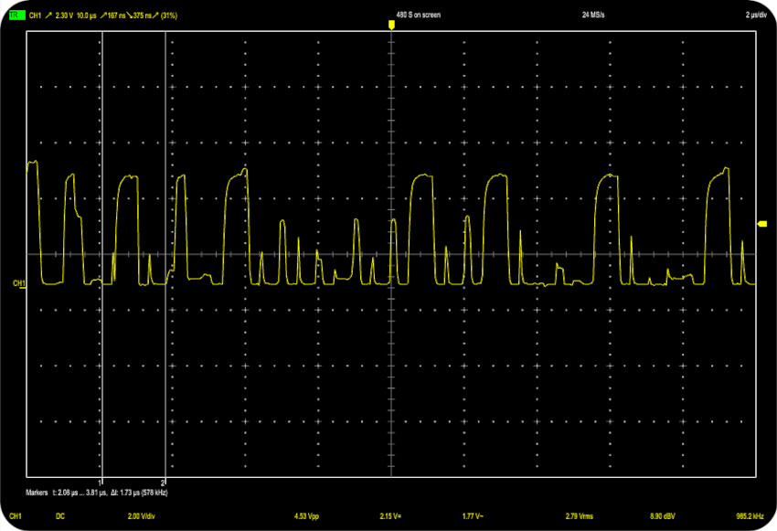
- VIC-II (pin 15) – Does the VIC-II generate a video signal ? Let’s take a look a the Sync/Luminance signal:
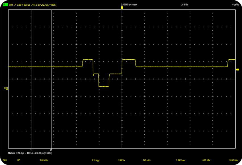
It sure does !
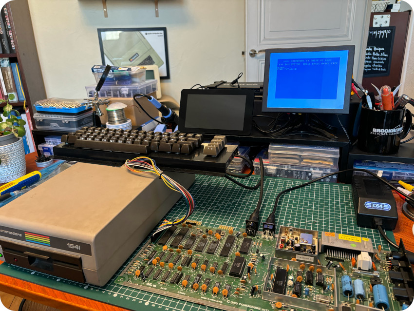
This sound really good, let’s plug in the AV cable:
Hurray ! It works !
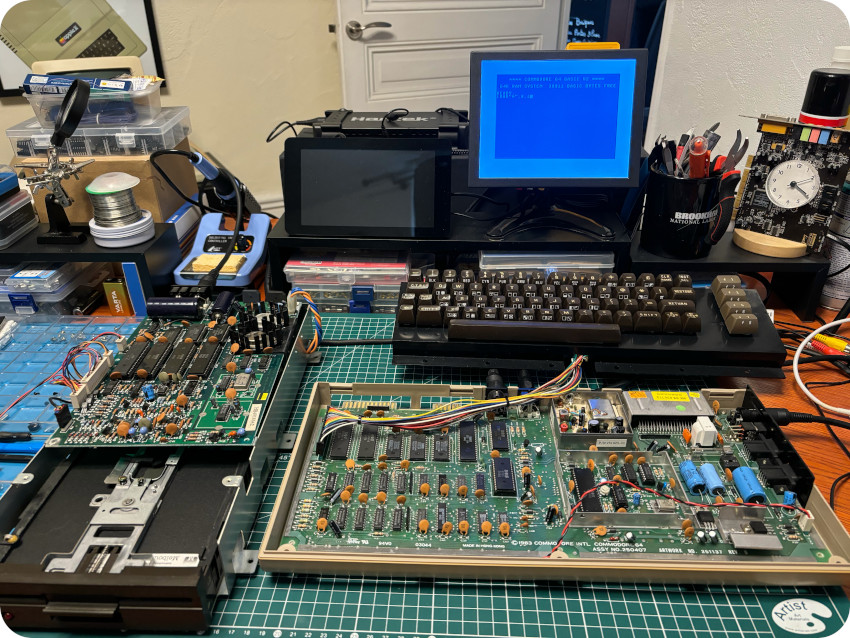
I wrote a few lines of BASIC for testing purposes. So far, it’s seems that my C64 is back to life !
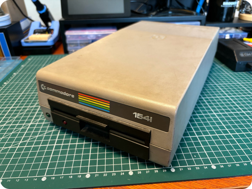
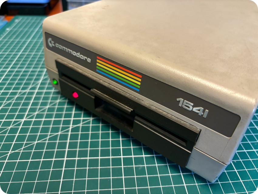
1541 DRIVE: FIRST RUN (AND FAIL)
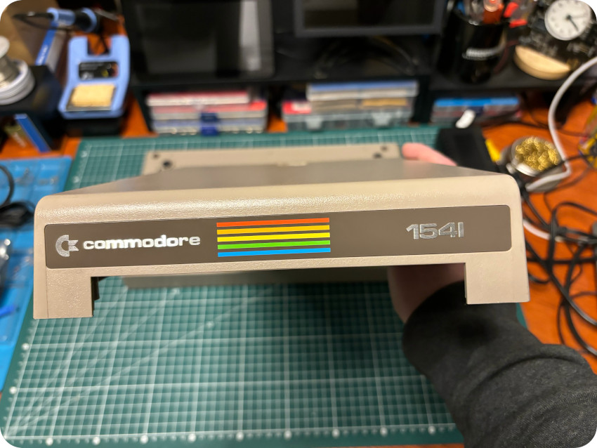
Let’s move on and focus on the Commodore 1541 floppy disk drive. Just like the C64, it was utterly disgusting:
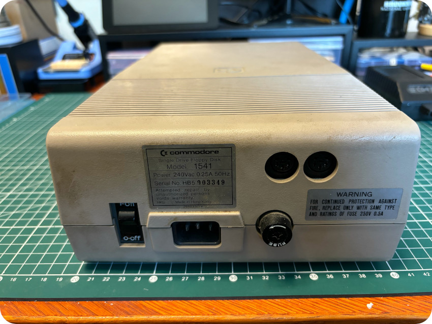
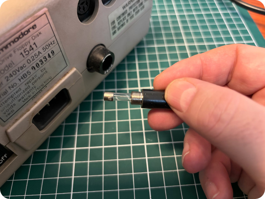
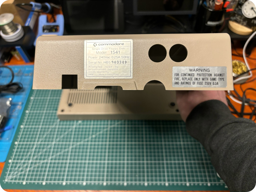
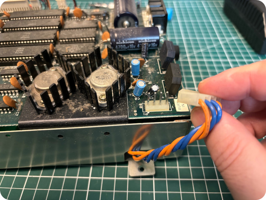
Let’s test the drive nevertheless. Before powering up the drive, I let’s take a look at the fuse:
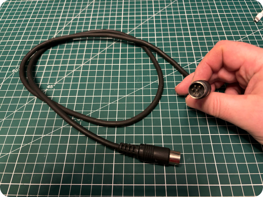
Everything’s fine so far. Now, let’s take a look at the power cable bundled with the drive. it was so unsafe (and filthy) that I used instead a brand new one (and e-wasted the old one):
The drive itself is an independent device, with its own CPU, RAM, ROM, etc. Upon power-up, it goes through its own internal diagnostic [from “Service Manual – Model 1540/1541 disk drive, Nov. 1985”].
Without connecting it to the C64, I powered up the drive:
- The green power LED went on: good
- The red activity LED went on, I could hear the drive spinning, the stepper motor and the head moving; good
- After a moment, the activity stopped (and the red activity LED went off, without blinking): good
So far so good:
- No electrical problem: the green LED won”t power up in case of problem with the +5 or +12V (or if the fuse had blown)
- No CPU or major IC’s (ROM, RAM, logic gates, logic array, etc.) failure: it this case, the red LED would have either flashed, stayed completely off or stayed permanently on (enabling troubleshooting guidance)
Let’s go one step further:
- I connected the drive to the C64
- I chose a diskette (Gyroscope, from Melbourne House)
- I powered-up the drive
- I powered-up the C64
- I tried to load the game (as precised on the floppy disk): LOAD “*”,8,1
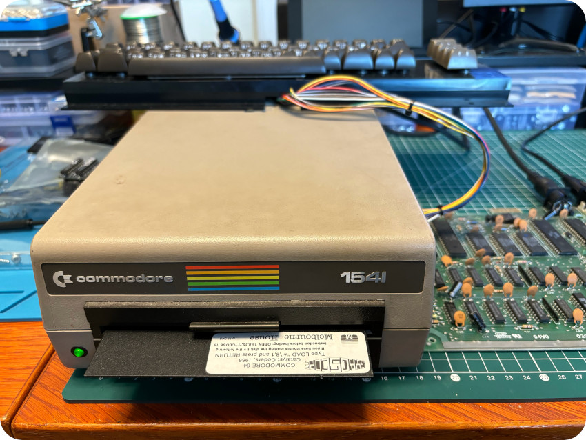
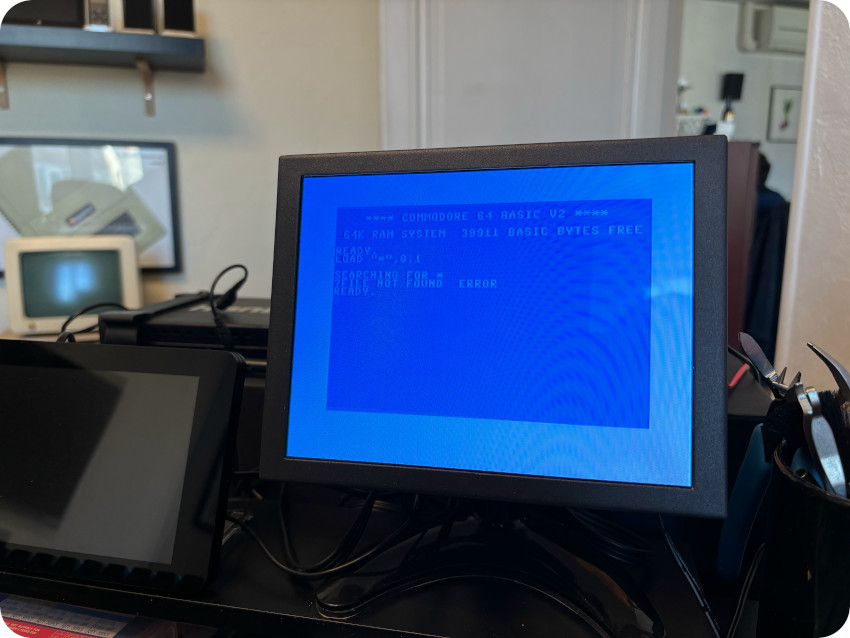
… and it failed with a “?FILE NOT FOUND ERROR” message.
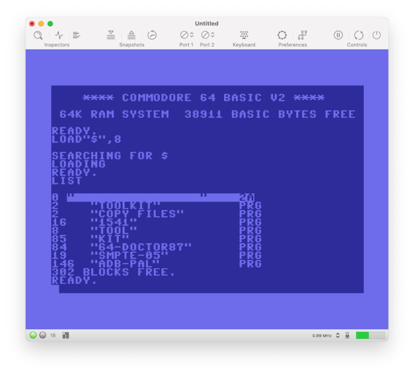
I did the same with 4 other floppy disks:
- I tried to list their contents (LOAD “$”,8 , then LIST)
- I tried to load games
All these tests failed.
According to the service manual, this could mean that:
- the drive head is dirty
- the 0 stop is not well adjusted
- the alignment is bad
Of course, it could as well be:
- bad diskettes (though they look very good)
- bad IEC cable (or connectors on both C64 and 1541 sides)
- bad CIA (#2) on the C64 side
- or … actually anything wrong with the 1541 PCB
The IEC cable was in good conditions, and I tested it for continuity, so I guessed a bad cable could be ruled out:
The floppy disks were in almost perfect conditions, so I doubted all of them would be bad. Let’s rule them out (at least for now).
It meant the most probable causes would be:
- a “physical” defect(s) on the 1541: dirt, misalignment, etc.
- a “logical” default(s) on the 1541: faulty RAM, ROM or any other component
- any defect on the C64 side:
- I checked continuity on the serial connector. It was Ok, so this can be ruled out
- A faulty CIA
Let’s hope for the best and go first with the “physical” defect hypothesis. I had to clean and service the drive anyway …
CLEANING THE 1541 DRIVE
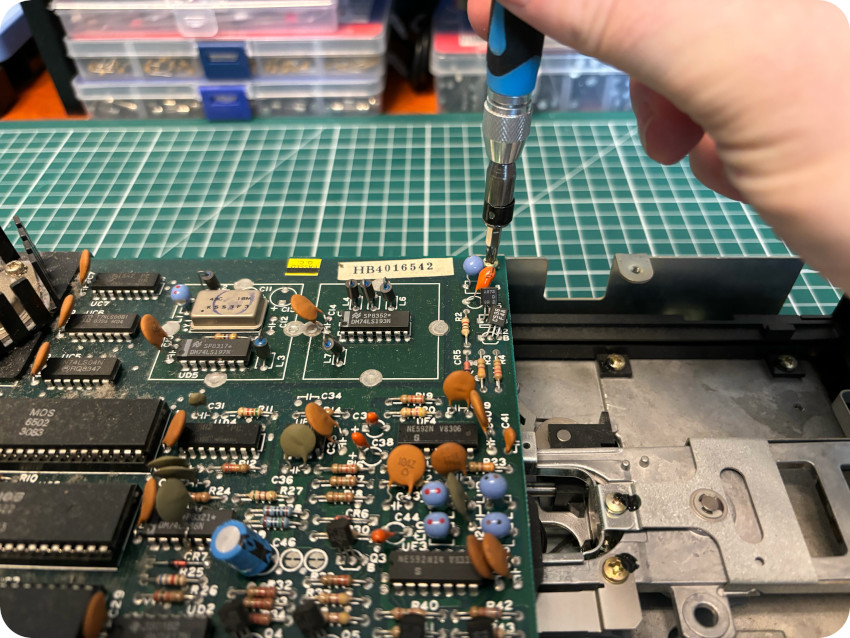
Opening the 1541 drive is quite easy, starting from the back and removing 4 screws:
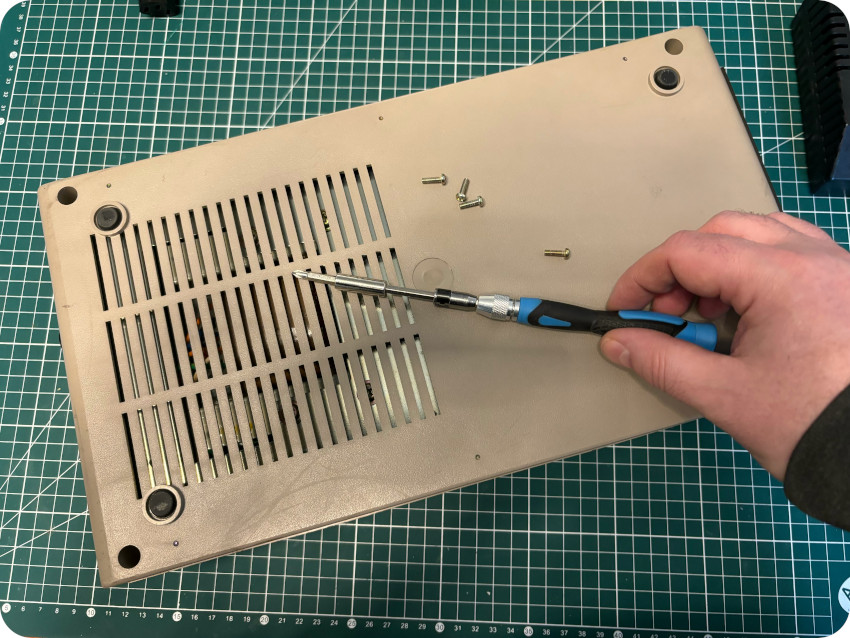
The top part of the enclosure can now be removed:
The following step is to flip the drive and to remove all the bottom part screws:
Let’s not forget the green power LED:
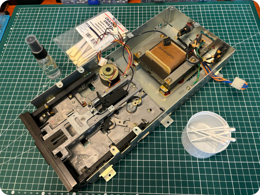
The drive itself (along with the transformer and PCB) can now be fully detached from the enclosure:
It is time for a thorough cleaning: warm soapy water, toothbrush, magic eraser, IPA and plastic rejuvenator:
It took me quite a while, but the results were pretty good:
SERVICING THE 1541 DRIVE
To service the drive, one has first to remove the PCB from the metal enclosure:
As you can see, it is quite dirty and dusty:
I detached all connectors and removed the PCB from the enclosure:
I started a long and thorough cleaning process with compressed air, cotton swabs, IPA, glass cleaning paper towels and a tooth brush:
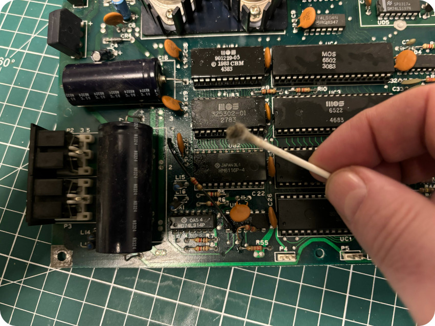
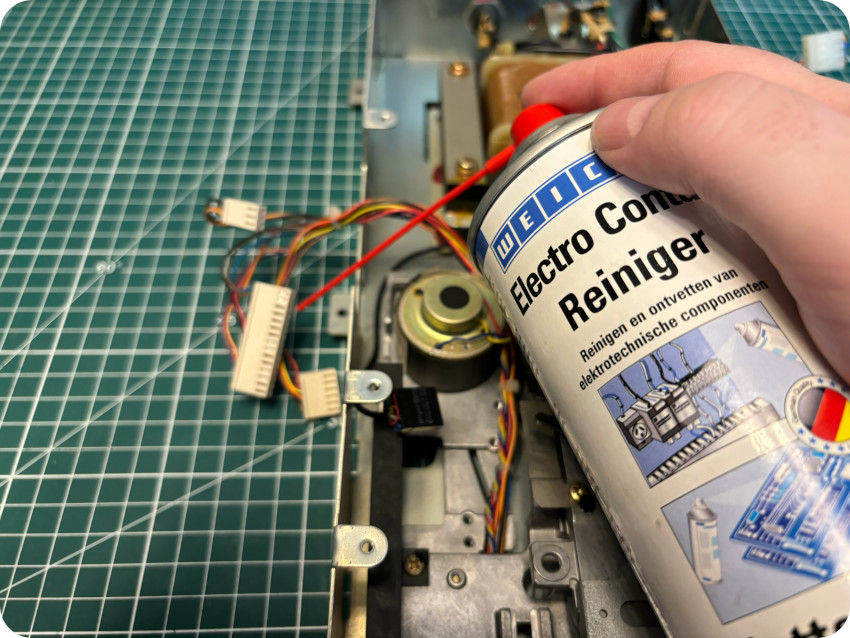
Once done, I sprayed contact cleaner on all connectors:
Once done with the PCB, I proceeded with the drive itself, the metal enclosure and the transformer (which weights a ton !):
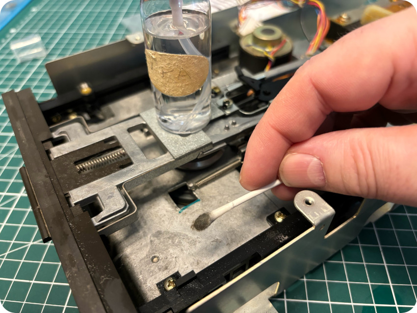
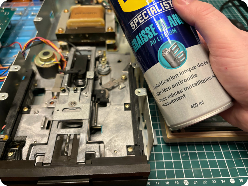
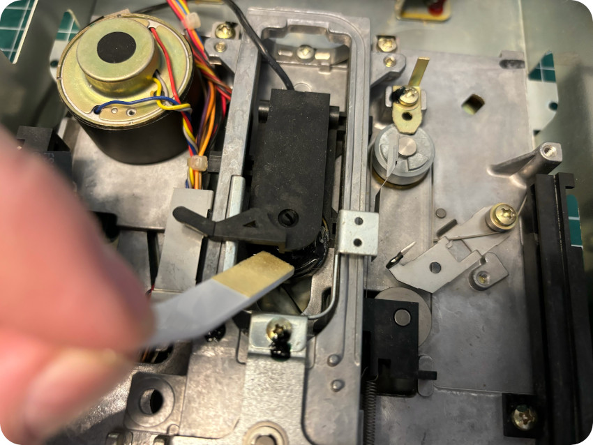
Then I used white lithium grease for moving parts:
And finally cleaned the head with a chamois swab soaked in IPA:
The belts and springs seemed fine, I did not touch them.
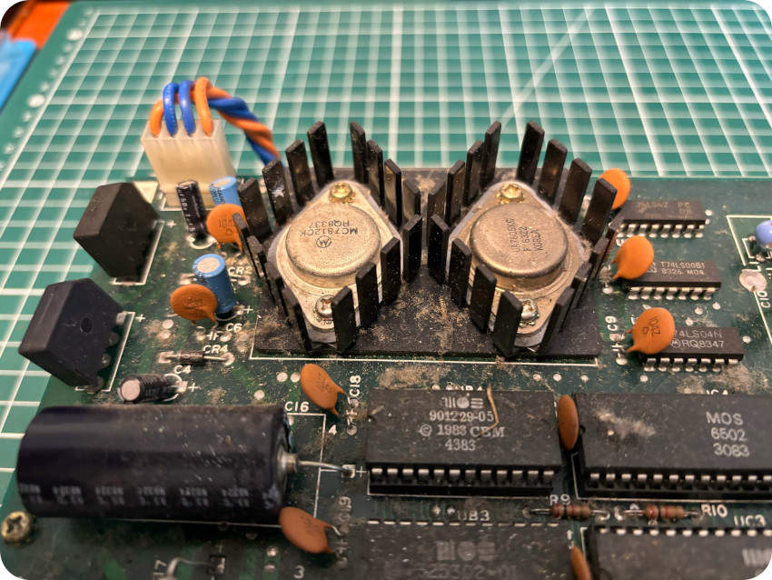
THE 1541 PCB
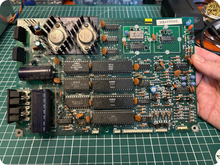
Let’s take a look at the 1541 PCB, from both sides:
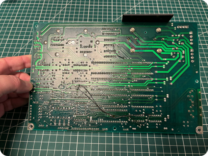
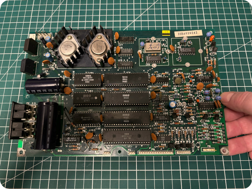
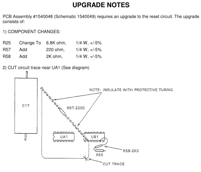
At first look, it seemed that there had been some kind of rework done. But this is not exactly the case. This is part of a documented upgrade to the PCB, done in factory (extract from “Service Manual – Model 1540/1541 disk drive, Nov. 1985”):
The board of my 1541 drive is a revision 1540050 (short board with ALPS drive mechanism, from 1982) with IC’s dated from 1983. Here are the main components:
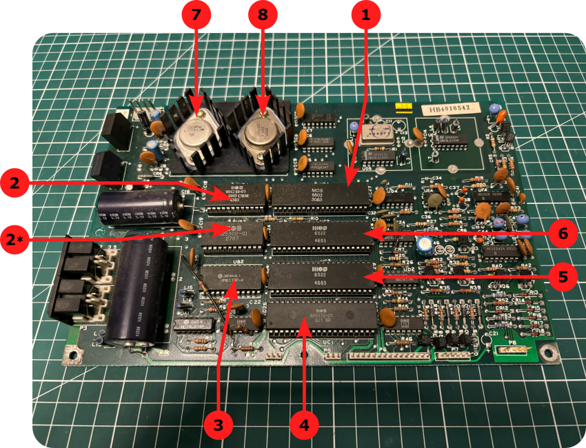
- Microprocessor (UC4): the 1541 drive uses a 8bit MOS 6502 CPU,
- ROMs (UB3, UB4): MOS 325302-01 (2, LoROM) and 901229-05 (2*, HiROM) DOS ROMs,
- RAM (UB2): 16K RAM (HM6116P-4 manufactured by Hitachi),
- Motor Controller (UC1): MOS 325572-01 Motor controller,
- VIA (UC2): MOS 6522 Versatile Interface Adapter (VIA) #1: Motor Control Interface,
- VIA (UC3): MOS 6522 Versatile Interface Adapter (VIA) #2: Serial Interface,
- Voltage Regulator (VR1): MC7812KC +12V voltage regulator,
- Voltage Regulator (VR2): UA7805KC +5V voltage regulator.
Note: see here for more details on components (as well as a troubleshooting guide)
1541 DRIVE (SECOND RUN)
Let’s find out if our problems were only caused by dirt and lack of grease. I plugged back the 1541 PCB, and tried once again the Gyroscope floppy disk:
I typed in LOAD “*”,8,1 (as written on the disk):
… and it actually worked this time ! Hurray !
Then I tried “Axis Assassin” …
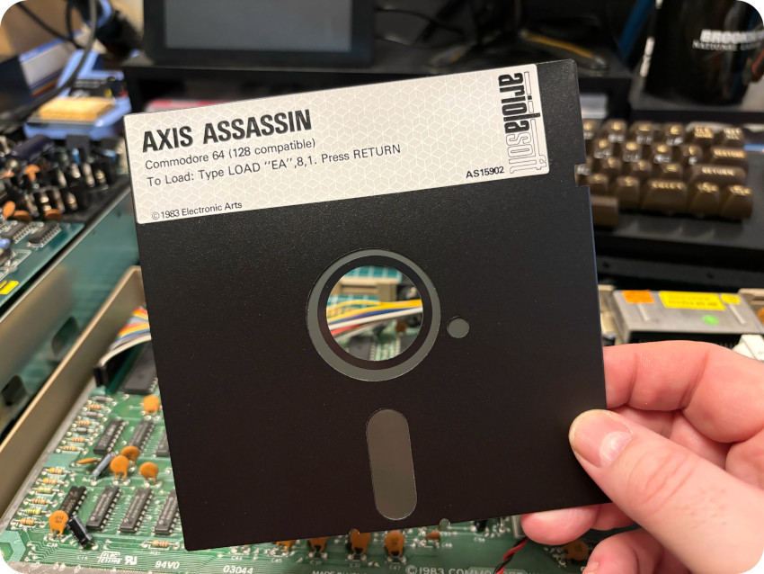
… which ran !
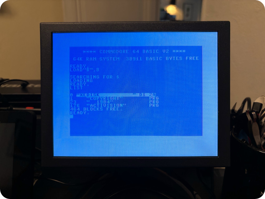
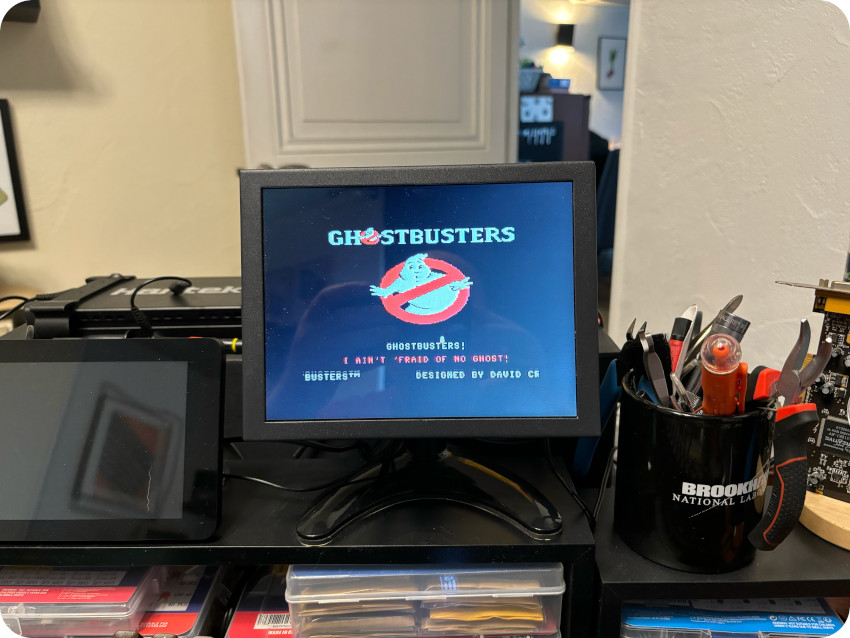
Then I tried the “Ghostbusters” floppy disk. Listing the content of the disk and launching the game worked !
Good ! Let’s put back things together:
Here is the 1541 floppy disk drive, in its 8bit glory, all cleaned up and serviced:
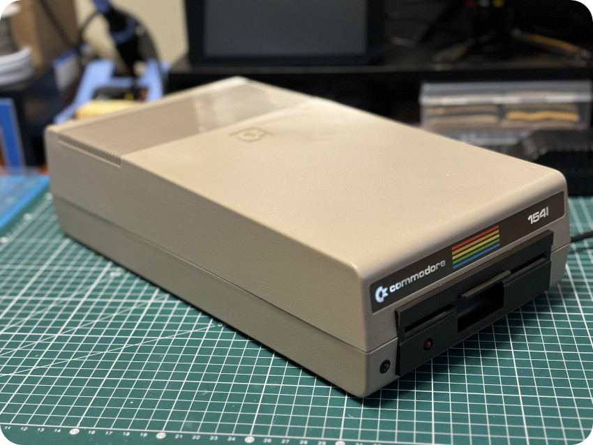
Let’s check that everything still works …

And it still works ! I connected the sound output to an audio amplifier in order to enjoy Ghotstbusters soundtrack:
Bustin’ makes me feel good ! And so does getting life back into dead vintage devices. I ain’t afraid of no ghost !
So far:
- The C64 is working (including the SID chip that I didn’t get a chance to really test until now)
- The 1541 drive is working
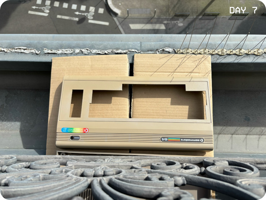
SUNBRIGHTING (PART 1)
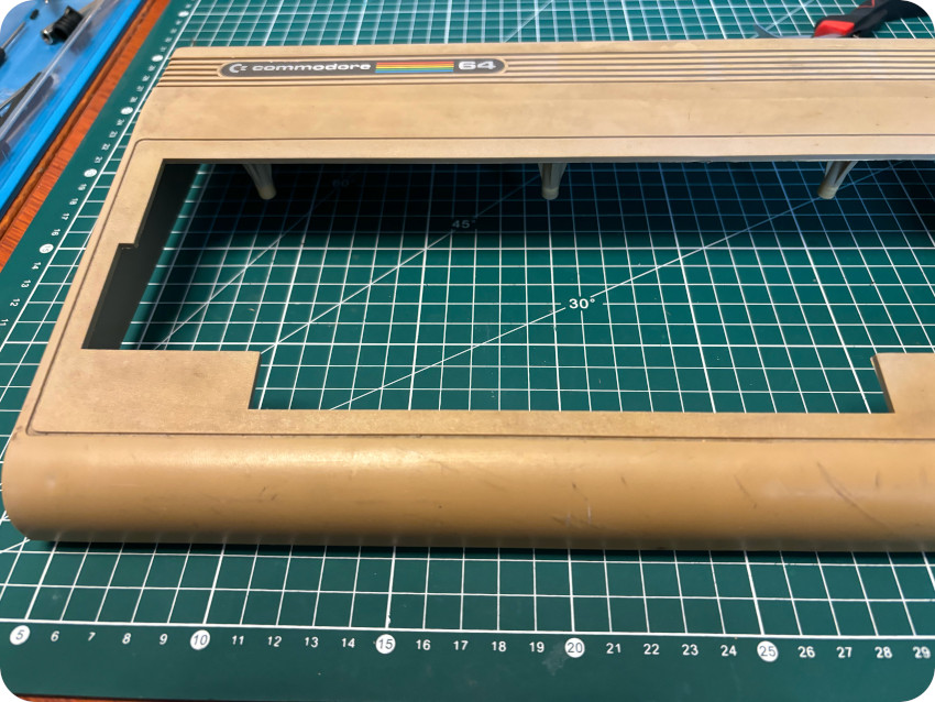
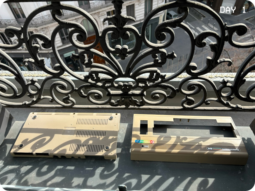
The enclosure of my C64 is yellowed. It is particularly true for the whole top part (badly yellowed) and the front of the bottom part (slightly yellowed), as seen on these pictures:
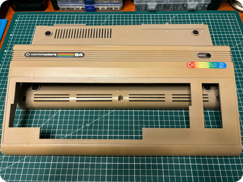
The difference is striking when comparing the Front / Top part (badly yellowed) to the Bottom / Back part (less yellowed):
Let’s take care of this ! As you may know, I had trouble when using peroxide cream on my Macintosh Plus. My usual process is therefore … less risky. I am using direct sunlight (heat + UV). It is a looooong process (>3 weeks, 5-6 hours a day), but I found it to be effective enough for my needs:
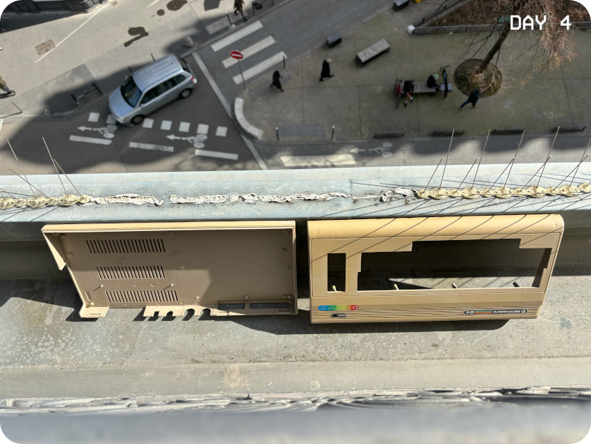
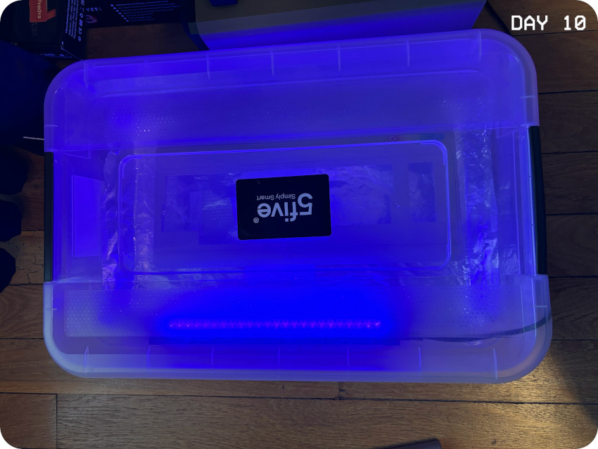
That been said … sunlight is rather scarce in France in January-February. So, to help me speeding up the process, I created a quick and dirty “UV box“, that I used the days where there was not enough sunlight:
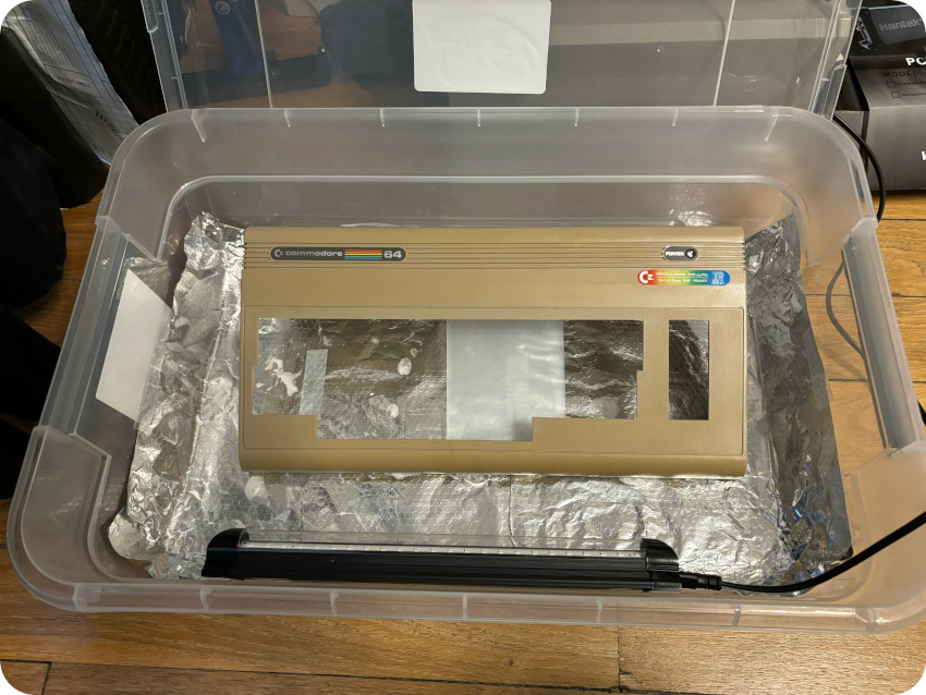
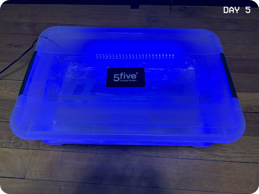
From there, it is a matter of … patience.
CARTRIDGE (ROBCOM COMBI-TURBOTOOL+)
While the enclosure was sun/uv-brighted, I had time to take care of the undescribed cartridge that was bundled with my C64:
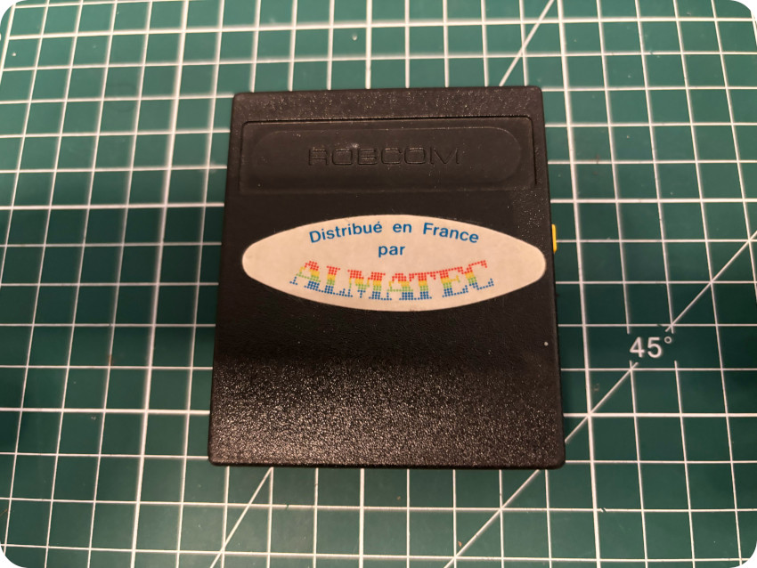
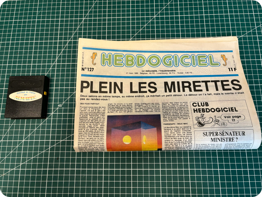
I started digging around to find information on this “ROBCOM” cartridge. It was distributed in France by ALMATEC (a subsidiary of PROCEP). I found a harsh review of this series of cartridges in the #127 edition of Hebdogiciel:
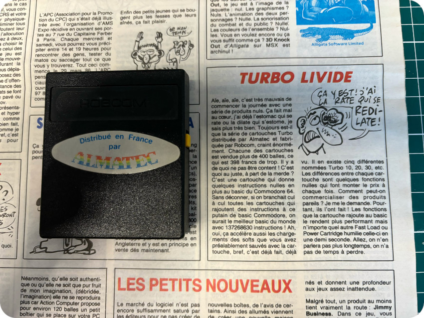
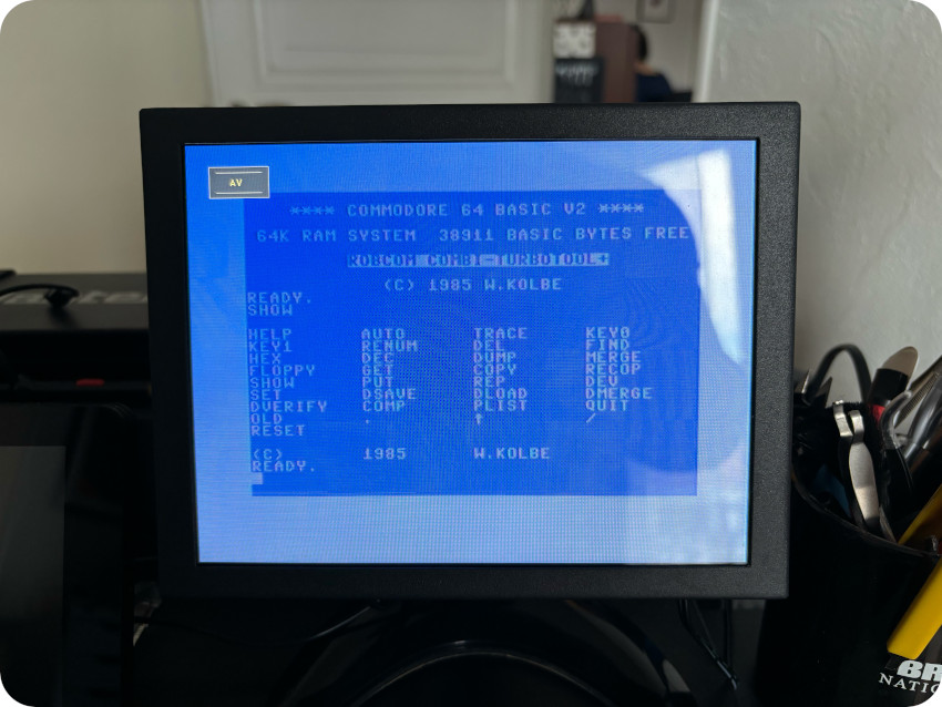
I found more details via the system-cfg.com forum, available here: “The Robcom TurboTool+ is a cartridge for the Commodore C64 computer with a BASIC-toolkit, function-keys and a fast loader/saver for disk (5x) and tape (10x). The Robcom TurboTool+ cartridge is made by Robcom in England. The software is developed by W. Kolbe in 1985.“
Let’s take a look:
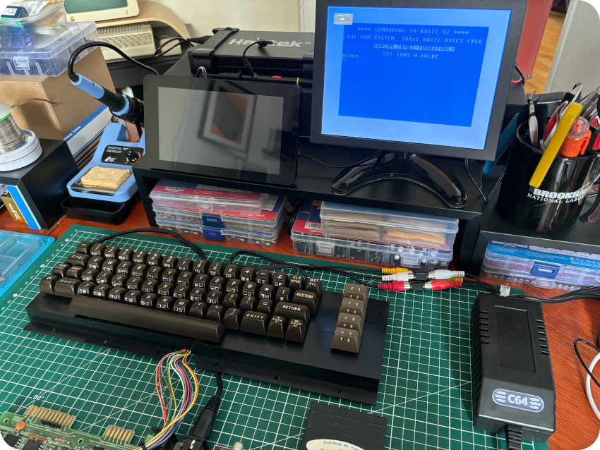
I typed in “SHOW” to get a list the extra BASIC commands provided by the cartridge :
It turned out, that the cartridge was also distributed by WEKA, and found its documentation here (PDF), though the Monitor isn’t included in the ALMATEC version of the cartridge. Nothing too exciting I must say, I tend to agree with Hebdogiciel that it wasn’t worse the price: 400F in 1985, or 128€ in 2024 (adjusted for inflation).
I decided to take a look inside:
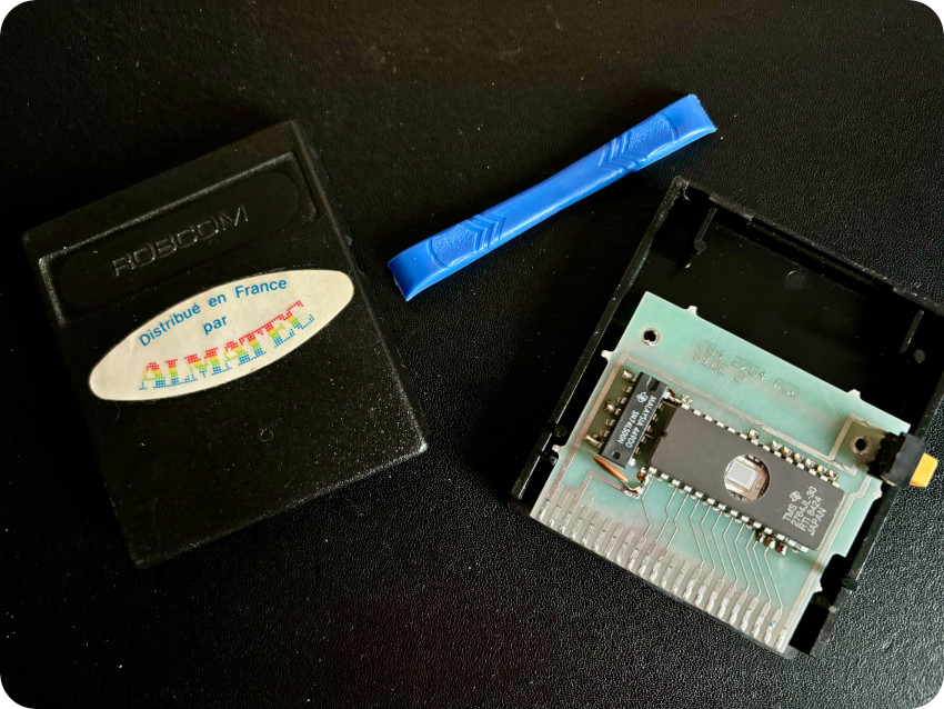
it is quite simple and uses a 28-pin 2764 EPROM. I guess it is possible to re-program it, but I don’t have the equipment for this yet. The window of the EPROM wasn’t taped, so I closed back the cartridge to avoid any UV damage.
SOFTWARE
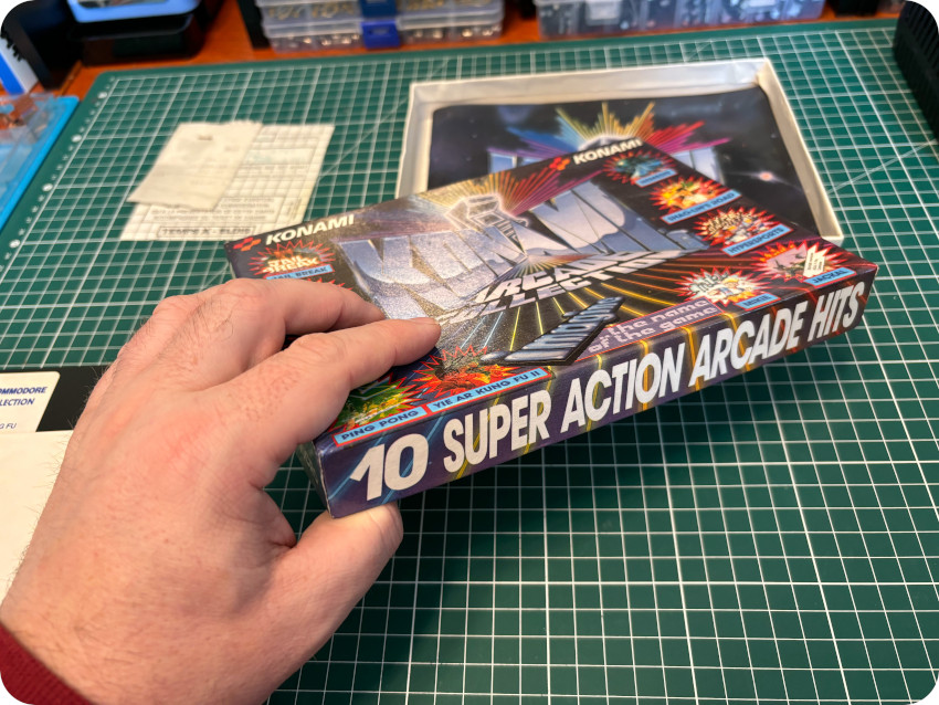
Let’s try some more software. First, let’s take a look at the boxed “Konami 10 super action arcade hits” set of floppy disks:
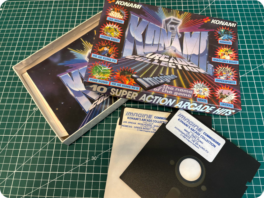
The box itself is a bit out of shape, and needed a bit of care:
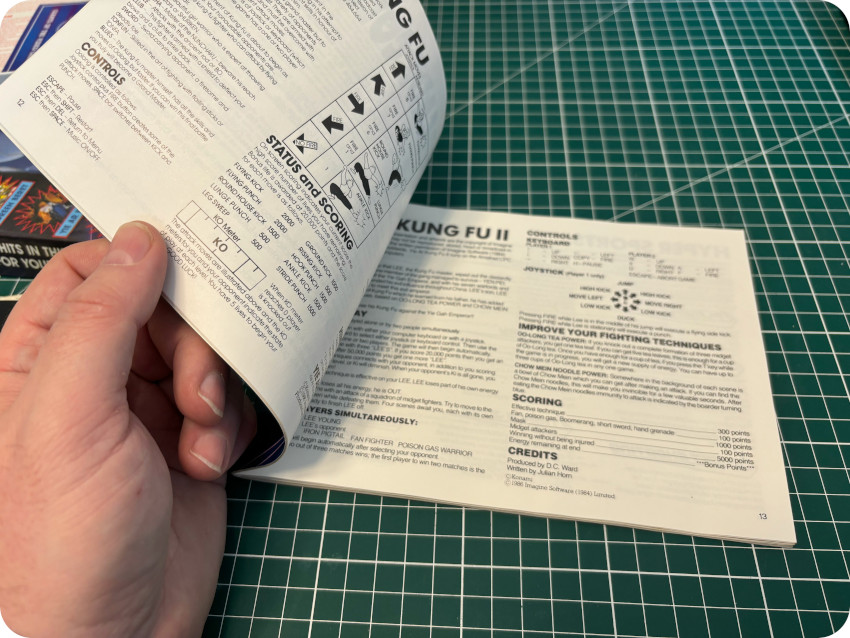
The included booklets are in good conditions:
Interestingly, I found inside the box the original receipt:
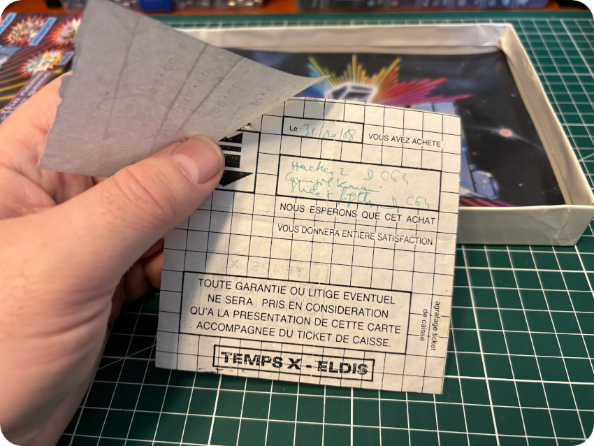
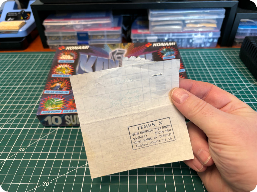
It is dated of the 31st of October 1988 and corresponds to the purchase of:
- Hacker II (120 F / 37€ adjusted for inflation),
- Konami’s compilation (225 F / 64€ adjusted for inflation) – the only remaining part included in the lot I bought,
- Street Fighter (215 F / 61€ adjusted for inflation).
The purchase was made at “TEMPS X – ELDIS”, inside the shopping center “Les Quatre Temps” (now “Westfield Les 4 Temps“) at La Défense, right in front of the CNIT (which was famous at the time for hosting the “SICOB” IT / computing show):
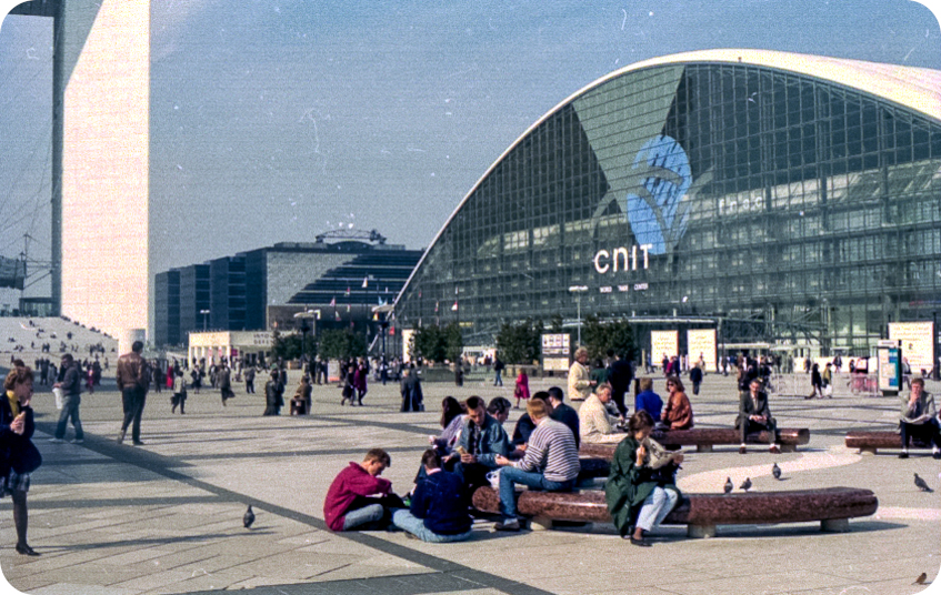
[CNIT in 1991 – from Wikipedia]
Interesting piece of memory. Anyways, I sanitized the box (to avoid any mildew propagation) and used 3 old hard drives (that fitted nicely) to put weight overnight, in order get the box back into shape:
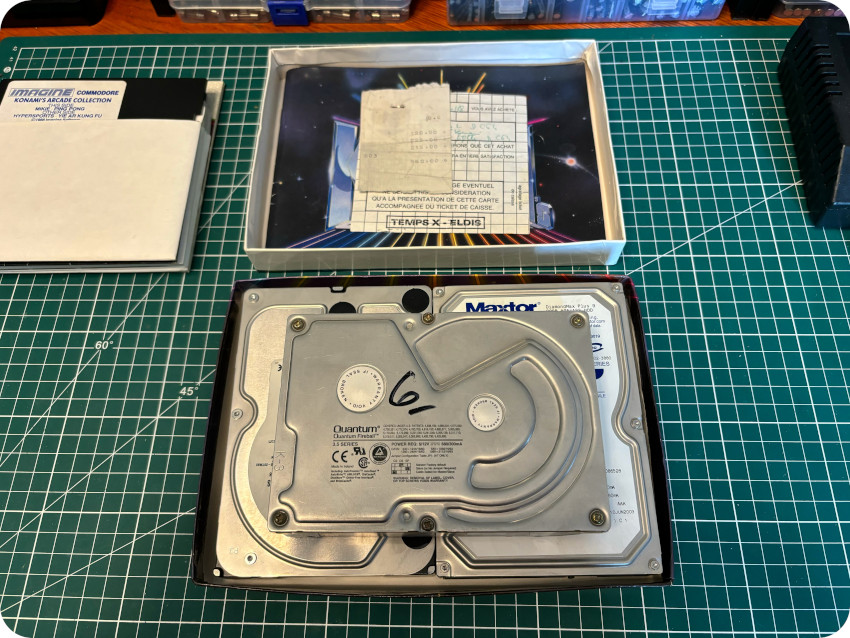
The final result isn’t bad at all !
The other boxed game was “Colossus Chess 4“. The box is in poor conditions (not sure how to repair the teared plastic cover, but I sanitized and cleaned it). The booklet and the floppy disk were in very good conditions. It seems it was bought at the Fnac retail store on the 5th of November 1988:
The other floppy disks were inside a plastic floppy box, that I cleaned up using my usual process (warm soapy water, IPA, anti static foam cleaner):
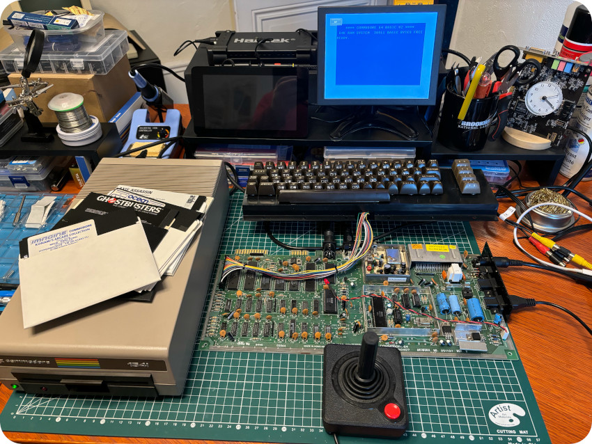
Let’s try them ! I plugged in my trusty Atari joystick clone and started loading games:
Here are a few screenshots:
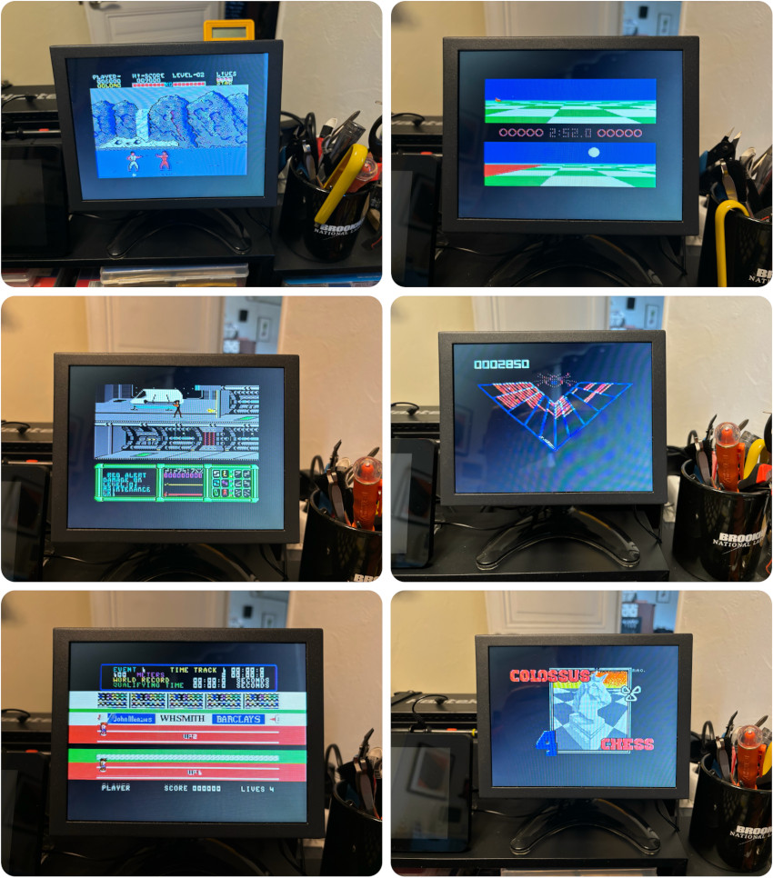
Almost all of them worked flawlessly. Only a couple of games from the same floppy (disk #2 of Konami’s compilation) failed. That’s pretty impressive for 40 years old floppy disks !
Note: loading software from 1541 drive is sloooow (at least when compared to disk drives I’m used to, like the Apple IIc’s or the Amstrad CPC464’s). If you want to know why (and a bit more about the VIA), have a look at these videos
- Why was the Commodore 1541 disk drive so slow ? and Update to my previous video on why the Commodore 1541 drive was so slow [Commodore History]
- The VIA Shift Register Bug and VIA shift register followup [8bit-times by André Fachat]
Note: because of the slowness of Commodore’s devices, fast loaders were available in various forms: software, hardware (cartridges, serial or user port dongles, …) and ROM’s. JiffyDOS, for example, replaces the Kernal ROM chip on the mother board and the DOS ROM chip on the disk drive.
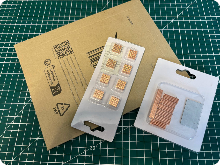
FUTURE PROOFING
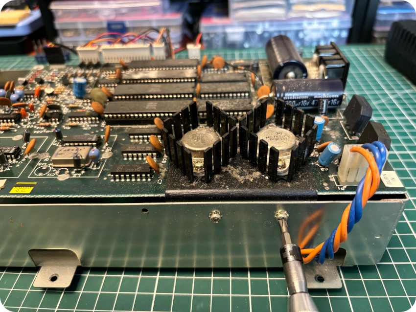
For the sake of preservation, I bought online sets of copper heat sinks of various sizes:
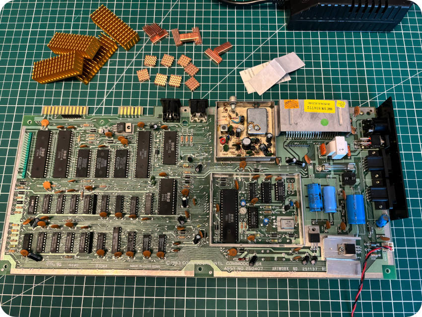
I protected with heat sinks the following IC’s: VIC II, SID, CPU, PLA and both CIA‘s:
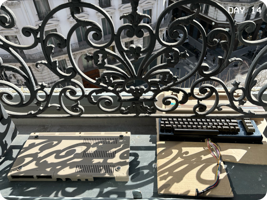
SUNBRIGHTING (PART 2)
Meanwhile … the sunbrighting process was still going on:
Since some of the keys were a bit yellowed, I included the keyboard into this long sun/uv-brighting process:
I stopped the process after 2 weeks, right at the beginning of March. Here is a little “Before / After” comparison:
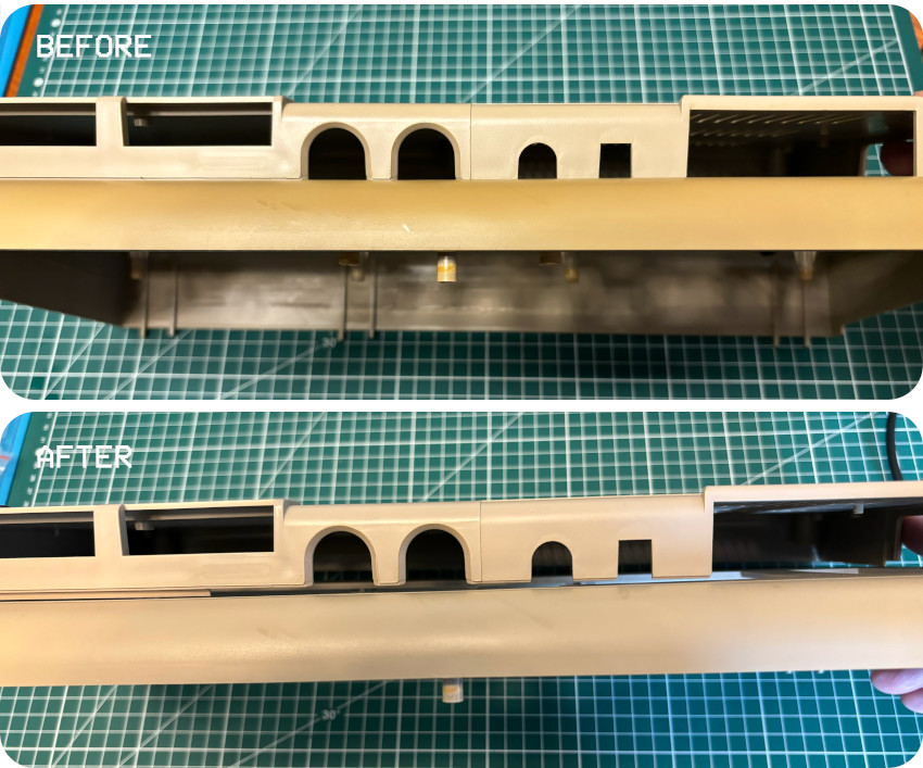
It is NOT perfect, but the effect is very notable. There are still traces of yellowing on some stubborn crannies that UV light won’t reach. But, all in all, I’m pretty happy with the results, and I don’t want to expose these precious (and brittle) plastic parts to UV / sun light too long.
Here is the final result:
Not bad ! Given from where it started (and the fact that it is still cold and not very sunny around here), I’m really happy with it !
MORE SOFTWARE AND XUM1541
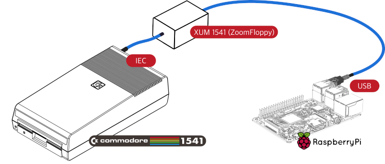
The Commodore 1541 floppy disk drive embeds its own CPU, ROM, RAM. It is basically … a computer, or at least, an independent device on its own, communicating via its IEC serial port. Given the proper cable and software, it is possible to drive a 1541 straight from a PC, Mac or any GNU/Linux device, without going through a Commodore 64. This allows to directly back up floppy disks and safely store corresponding images for preservation purposes on a PC. Conversely, it allows to create new floppy disks from preserved images directly from a PC.
For this, we will need:
- A X1541-like cable: the X1541 series of cables are used from a PC, Mac or GNU/Linux device to access IEC devices. Typically, a PC connects to the floppy disk drive via such a cable, in order to copy data to and from disks. Several versions of the X1541 cable exist like the X1541, XM1541, XA1541, XU141 / USB2IEC or XUM1541 / ZoomFloppy.
- A software stack: openCBM is an open source software for MS Windows, macOS or GNU/Linux that interfaces with Commodore specific IEC serial devices. It provides a low-level library and command-line tools for copying data to and from floppies [from https://www.c64-wiki.com/wiki/OpenCBM]. OpenCBM is available here on GitHub.
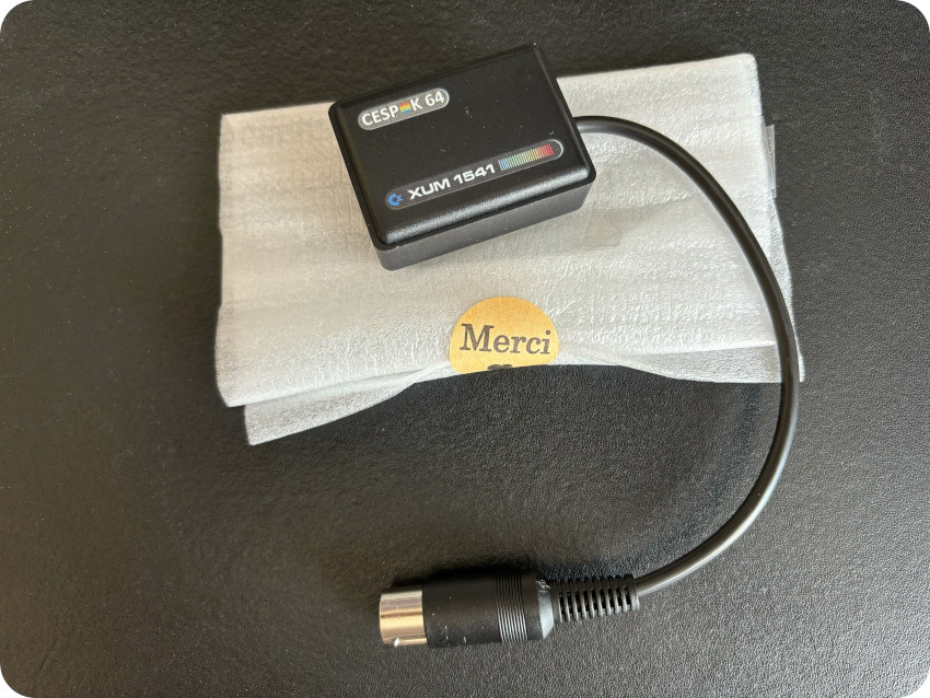
I ordered a XUM1541 from Spain on eBay (from https://www.ebay.fr/str/cespok64). Unfortunately … after over a month of waiting, it got lost in the mail. So I contacted the seller who very nicely agreed to send me another one only for the cost of tracked shipping. A week later, it finally arrived:
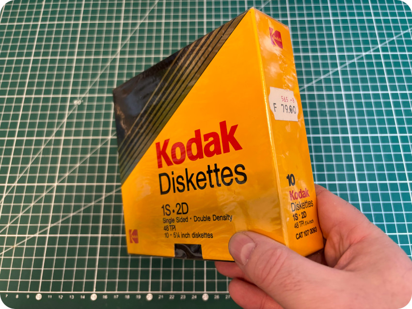
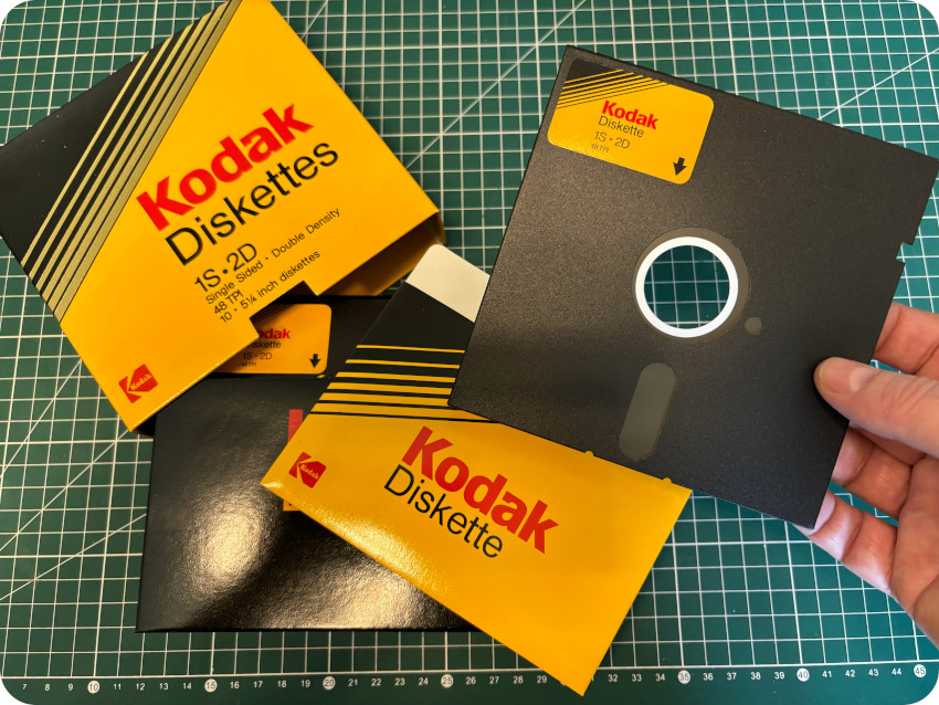
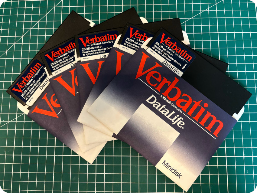
Meanwhile … since the only 5″1/4 disks I had in stock were 4-5 remaining Verbatim 2S/2D floppies (that were bundled with my Apple IIc), I bought on LeBonCoin a nice sealed box of Kodak floppy diskettes (for far less than the 79 F – 24 € now – price tag on the box):
We have now all what is needed on the hardware front !
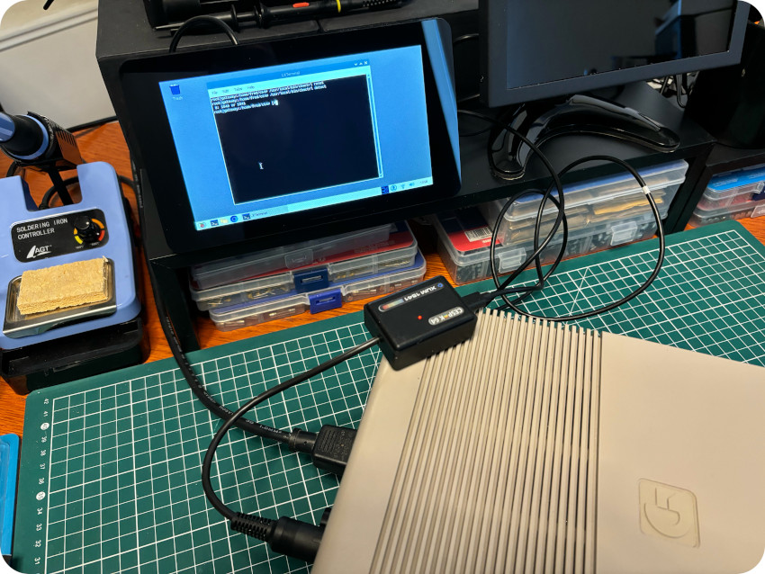
On the software front, here are the main steps to compile and install openCBM and the XUM1541 plugin on a Raspberry Pi (Raspian GNU/Linux 11) :
- Install (as root) the necessary dependencies: apt-get install libusb-dev libncurses5-dev
Note: I added tcpser (see first screenshot) to the list for testing purposes, but it is not needed here. - Download the openCBM sources (opencbm-0.4.99.104.tar.gz) from here
- Once extracted (tar xvzf opencbm-0.4.99.104.tar.gz), build OpenCBM with: make -f LINUX/Makefile opencbm plugin-xum1541
- Once done, install (as root) with: make -f LINUX/Makefile install install-plugin-xum1541


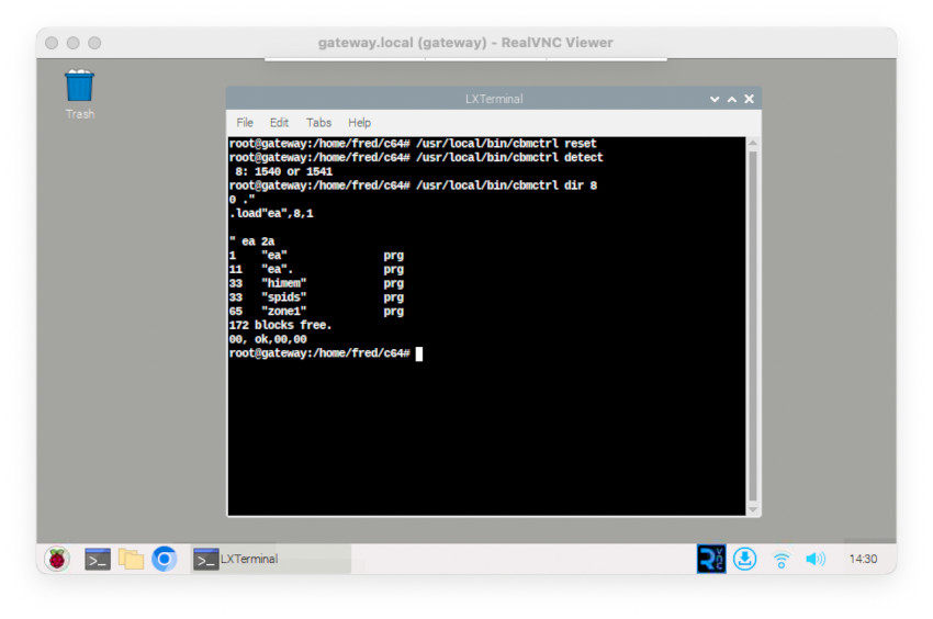
Here are the utilities provided by openCBM that I used:
- cbmctrl: command line utility for direct device access. See here for documentation.
Synopsis: cbmctrl [global_options] ACTION [action_args]
Examples:- cbmctrl reset: resets all drives on the IEC bus,
- cbmctrl detect: detects all drives on the IEC bus and outputs their ID’s
- cbmctrl status 8: ouputs status of drive 8
- cbmctrl dir 8: lists the directory of the floppy disk in drive 8
- cmbformat: fast low-level disk formatter for 1541,1570 and 1571 drives. See here for documentation.
Synopsis: cbmformat [OPTION]… DRIVE# NAME,ID
Example:- cbmformat 8 GAMES,42: formats standard disk (35 trakcs) in drive 8 (named “GAMES” and ID’ed “42”)
- d64copy: fast disk image transfer (read and write) utility for 1541,1570 and 1571 drives. See here for documentation.
Synopsis: d64copy [OPTION]… SOURCE TARGET
Examples:- d64copy 8 image.d64: reads the floppy in drive 8 and creates a .d64 image (named “image.d64”) from it
- d64copy image.d64 8: writes a .d64 image (named “image.d64”) to the floppy in drive 8
Let’s try ! Here is generic the process to use the XUM151:
- Connect the XUM1541 to the Raspberry Pi (micro-USB male to USB type-A in my case). Make sure you cable handles both power+data (I struggled for a while before realizing I was used a power-only cable). The red LED on the top turns on
- Power OFF the 1541 drive
- Insert the DIN-6 plug into one of the two IEC connectors on the back of the 1541 drive
- Turn the 1541 drive ON
- Use openCBM utilities from the command line …
I used the cbmctrl utiliy and issued a reset action followed by a detect action:
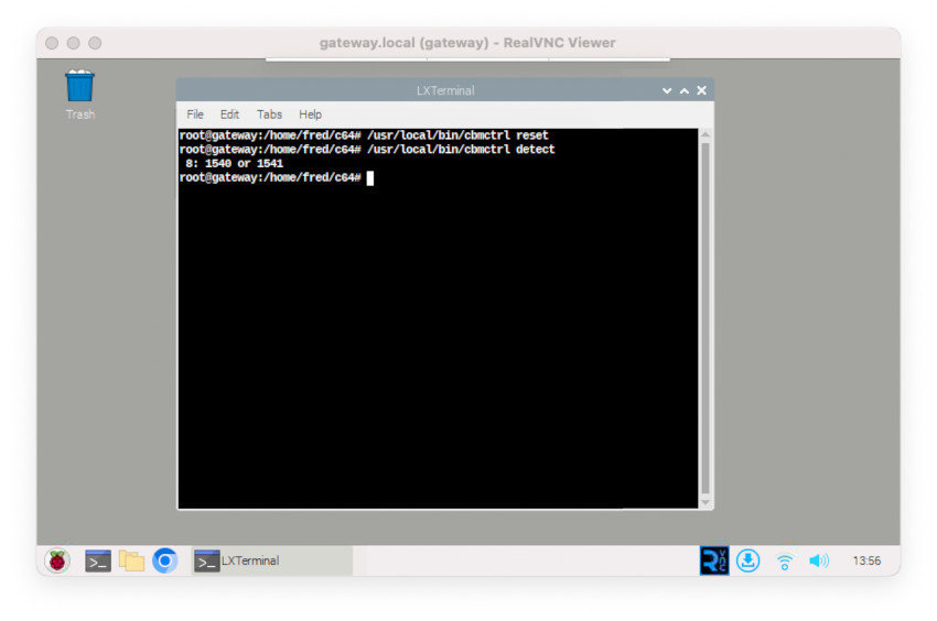
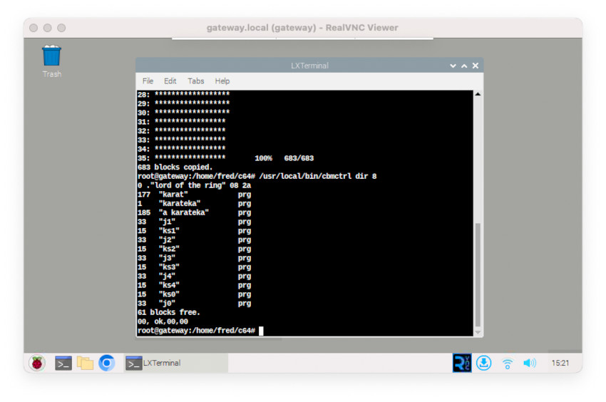
And it worked right away ! Then I inserted a floppy disk into the 1574 drive, and issued a dir action:
And … it listed the content of the floppy disk:
Good ! Let’s move on an create new floppy disks from .d64 images. I uploaded a bunch of .d64 collected on the Internet to the Raspberry Pi:
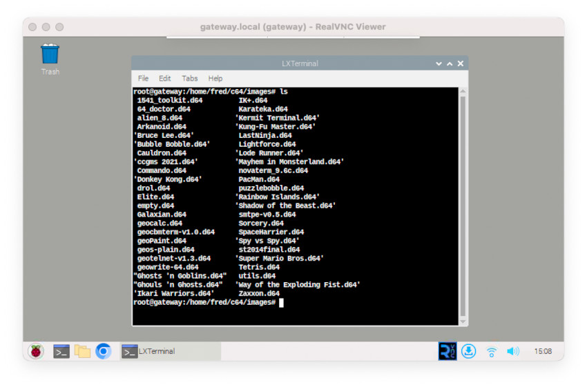
I inserted a fresh floppy disk in the drive:
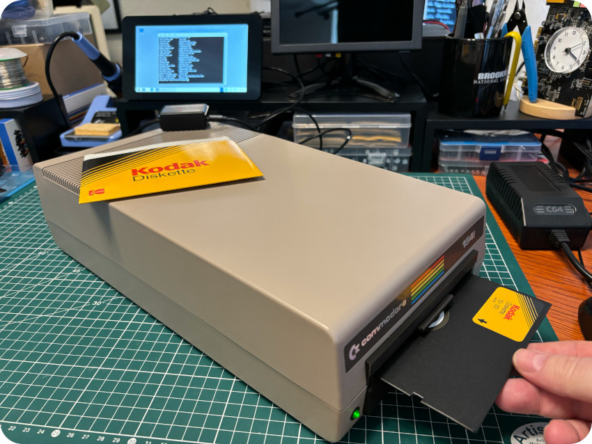
Then, I used openCBM to format the floppy disk, copy a .d64 image (Karateka) to it and dir the content: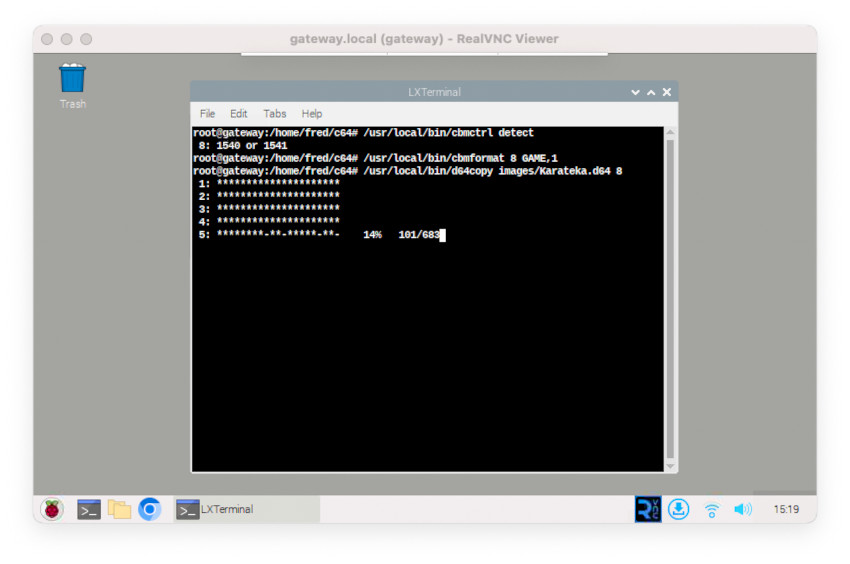
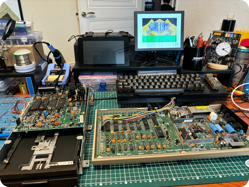
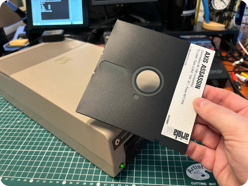
The next step was, of course, to test this newly created floppy disk on the Commodore 64 itself, and run the game :
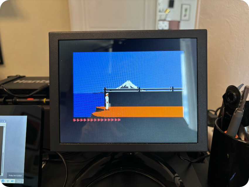
And it worked perfectly fine ! So I went one and created batches of floppy disks straight from .d64 images. How nice !
For testing purposes, I needed also to create a customized image, with multiple system tools inside. To create such customized .d64 images, I used the VICE emulator and its c1541 utility. This command is a disk image utility which allows – among other things – to attach images, extract files or add files to it:
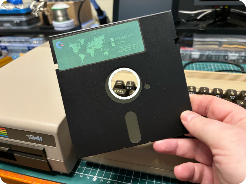
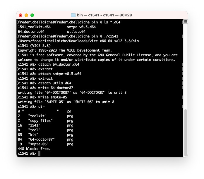 This way, I could create a “System tools” .d64 image disk with these utilities:
- The 1541 Toolkit: disk utility
- 64 Doctor: system tester (RAM, keyboard, video, audio, disk drive, …)
- SMTPE: color bar generator to check video / color outputs
- Adrian Black’s 8bit dance party (PAL version)
Here’s the content of the customized .d64 image, loaded on the VirtualC64 emulator for macOS, so I could test it before writing it to a floppy disk:
Once the customized .d64 tested, I created the “System tools” floppy disk.
To created double-sided floppy disks, I used the good old trick of cutting a notch on the left side of the disk, so that the 1541 drive would allow to write on the flipped side of the disk (otherwise, the 1541 sensor would have thought it were write-protected):
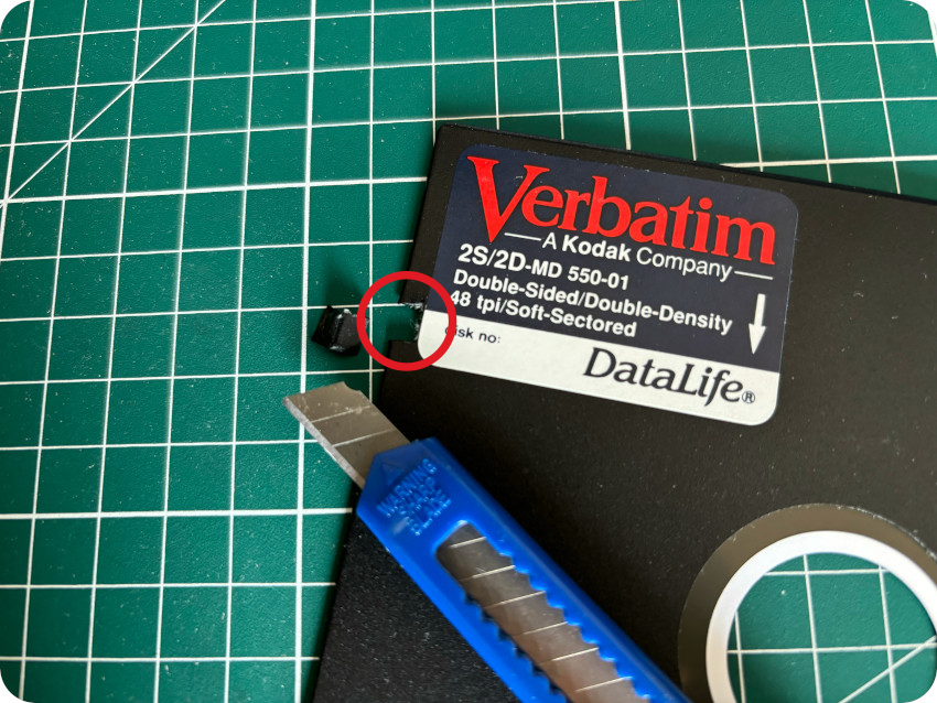
Here is the result for my remaining Verbatim 2S/2D floppy disks:
As a finishing touch, as I always do, I used Inkscape to created labels and sleeves (based on the models I created for my Apple IIc):
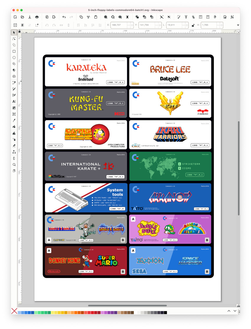
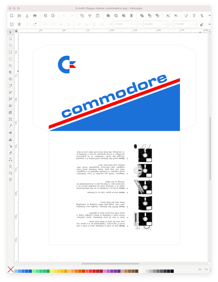
Here is a picture of a batch of re-created floppies:
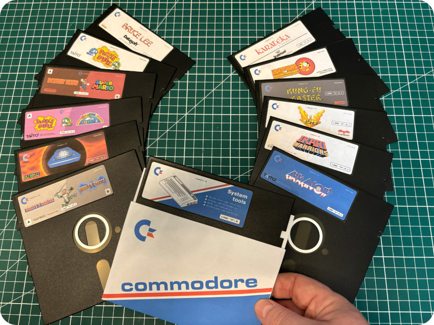
Note: as always, these artworks are not meant to be perfect replicas, but are just meant to be fun and as much era appropriate in their looks as possible.
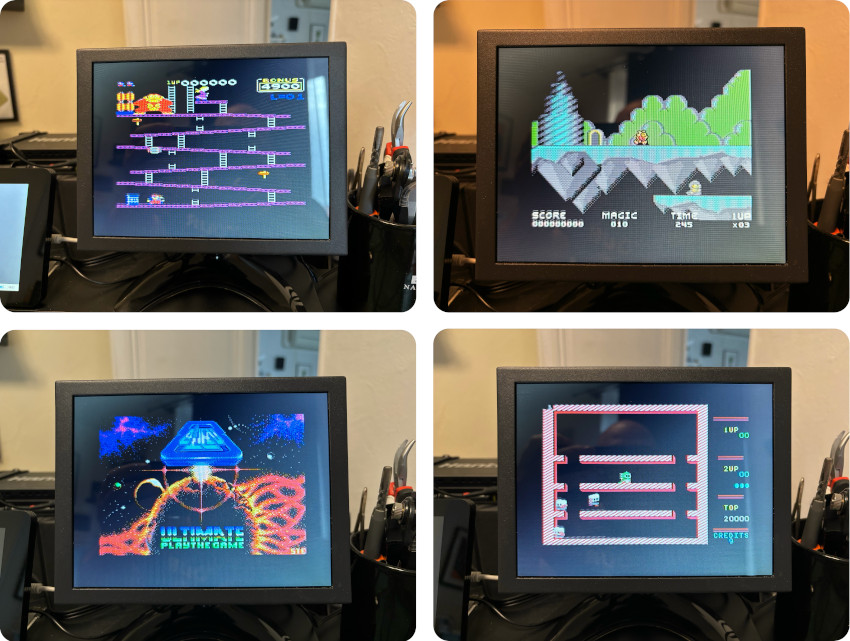
And here are screenshots:
Meanwhile … I was gifted for my birthday an AV (Composite / S-Video) to USB converter:
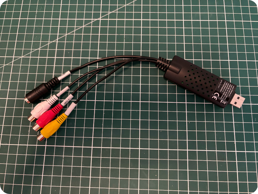
This allowed me to use OBS Studio on my Mac to capture Audio / Video outputs from my C64, straight out of my home-made AV cable:
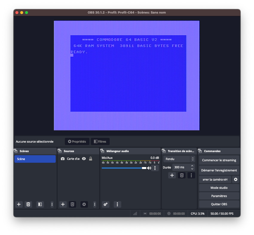
The resulting videos are not high quality, but it was easy and fun to produce (and what a good excuse to learn a bit how to use OBS Studio to capture or stream videos). Here are a few of them:
| Kung-Fu Master |
| Ghost’n Goblins |
| Arkanoid |
| Adrian Black 8 bit dance party |
NULL MODEM CABLE AND NETWORK ACCESS
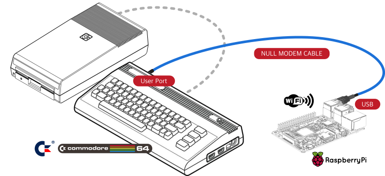
I like to connect old computers to the internet. I followed the same principles that I used for my Apple IIc, Macintosh Plus and Atari ST: using a null modem cable and a GNU/Linux-based gateway:
- Connect the Commodore 64 to the Raspberry Pi via a null modem cable (from the C64 User Port to a USB port on a Raspberry Pi, via a RS232 adapter)
- Use a Raspberry Pi (connected to my home network via WiFi) as a gateway for internet access
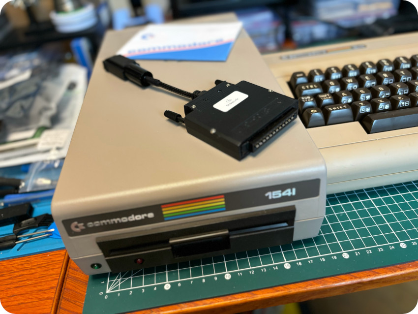
In the case of the C64, what I actually needed to build is often called “StrikeLink“. It is a null modem that converts TTL signals to RS232 and vice versa. Here are a few links on this matter:
- RS232 on a Commodore 64: https://www.youtube.com/watch?v=5xKASpZIoc8 and https://github.com/josipk/RS232-Commodore64/tree/main
- Build your own StrikeLink: https://1200baud.wordpress.com/2012/10/14/build-your-own-c64-2400-baud-usb-device-for-less-than-15/
So, I ordered:
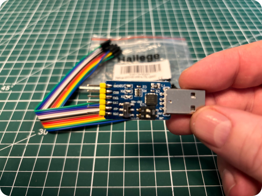
- A CP2102 USB to UART (TTL) adapter and Dupont cables (on Amazon)
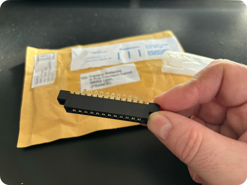
- A User Port connector (on eBay, from Italy)
- A DB37 shell (on Amazon), to protect and secure the User Port side (DB37 shells fit nicely the User Port):
- A plastic HDMI shell (on Amazon), to protect the USB side (I could not find any USB shell that would fit, so I figured an HDMI shell would do the trick):
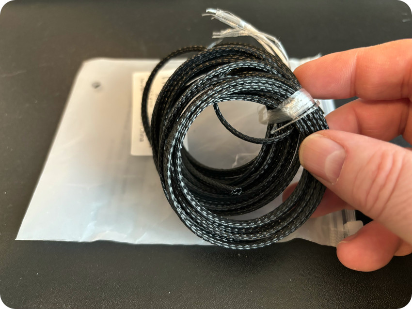
- Braided tubing (on Amazon), to protect the Dupont cables:
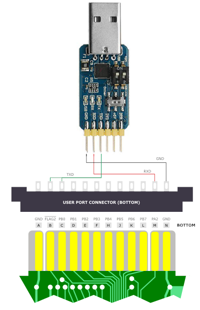
The wiring is pretty simple:
- Connect the TxD pin from the TTL adapter to pins B and C on the User Port connector (RxD)
- Connect the RxD pin from the TTL adapter to pin M on the User Port connector (TxD)
- Connect the GND pin from the TTL adapter to pin N on the User Port connector (GND)
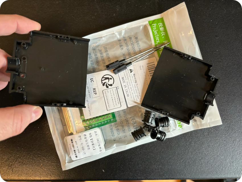
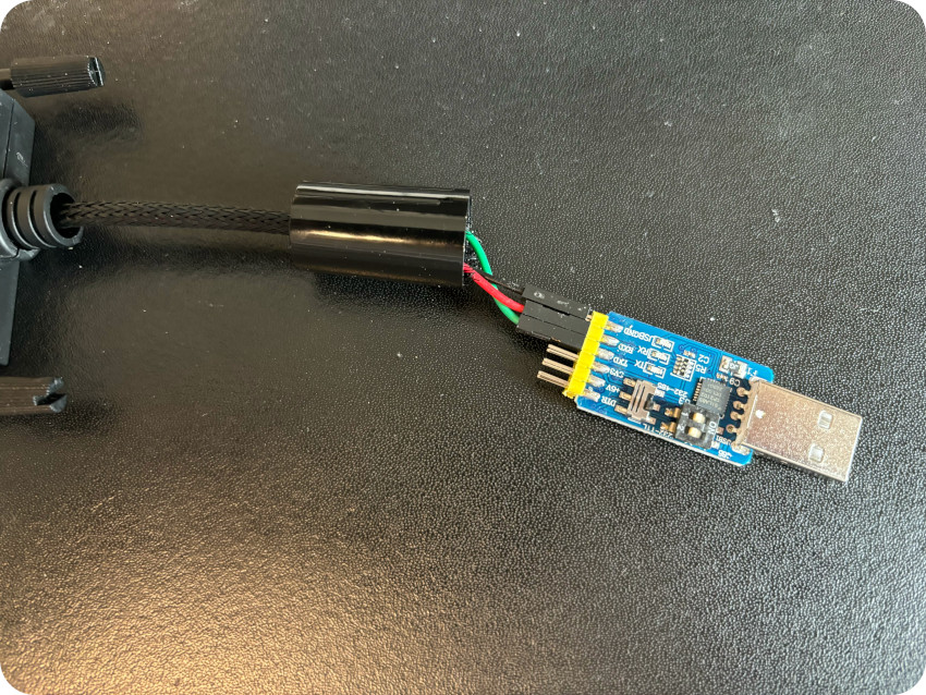
Here are a few pics of the building process:
- Soldering Dupont cables to the User Port connector (and jumping pins B & C)
- Connecting the Dupont cables to the USB / TTL adapter:
- Securing the User Port connector with a DB37 shell and tubing, that fitted both with a bit of fiddling:
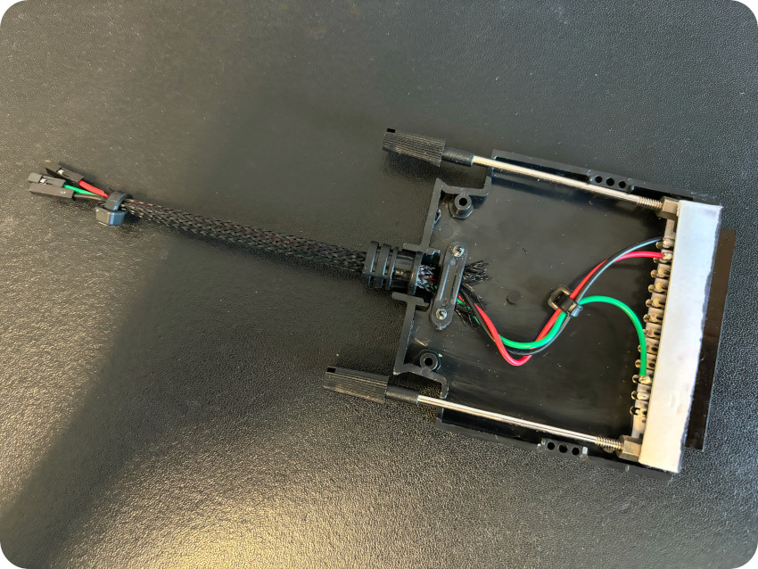
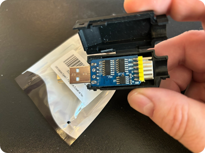
- Securing the CP2102 USB to UART (TTL) converter with the HDMI shell. I had to thin and cut some inner edges nevertheless for the converter to fit in. With the help of double-sided sticky tape, I ended up with this contraption:
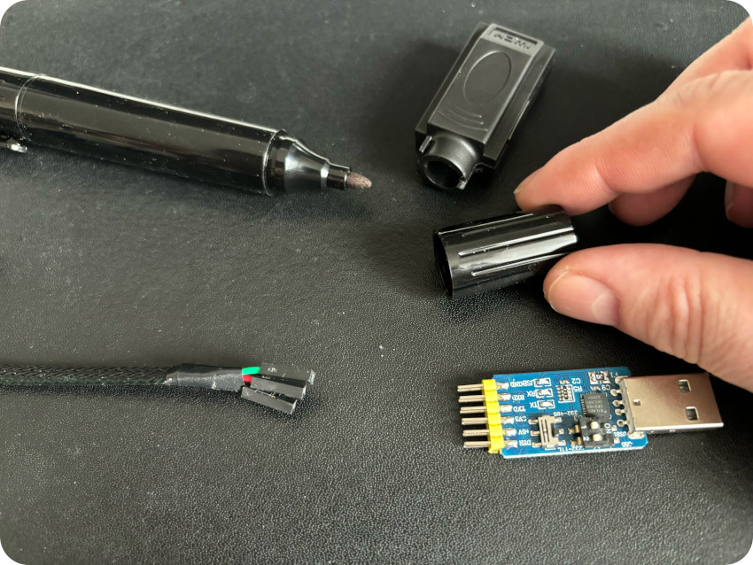
To connect the Dupont cable to the pins, I had to cut parts of the back of the HDMI shell. Alas, it looked a bit crooked and uneven, so … since my OCD’s were acting up because of that, to cover the missing parts, I used the cap of an used black sharpie, into which I drilled a small hole to let the breaded tubing pass through:
Before going any further and close the connector, I gave the UART bridge a try. I plugged it into my Raspberry Pi, and the GNU/Linux system recognized right away the CP2102 USB to UART bridge controller. It assigned the converter to device /dev/ttyUSB0: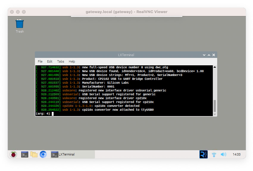 There are three LED‘s on the top on the bridge (GND, RXD and TXD lines). I grounded the GND pin, and the yellow GND LED went up. Then I tried echoing (strings) through /dev/ttyUSB0. But not matter what, the TXD (blue) LED stayed quiet and wouldn’t indicate any data flowing out. The bridge came without documentation whatsoever, so I played randomly with the switches and ended up with this configuration (both switches up):
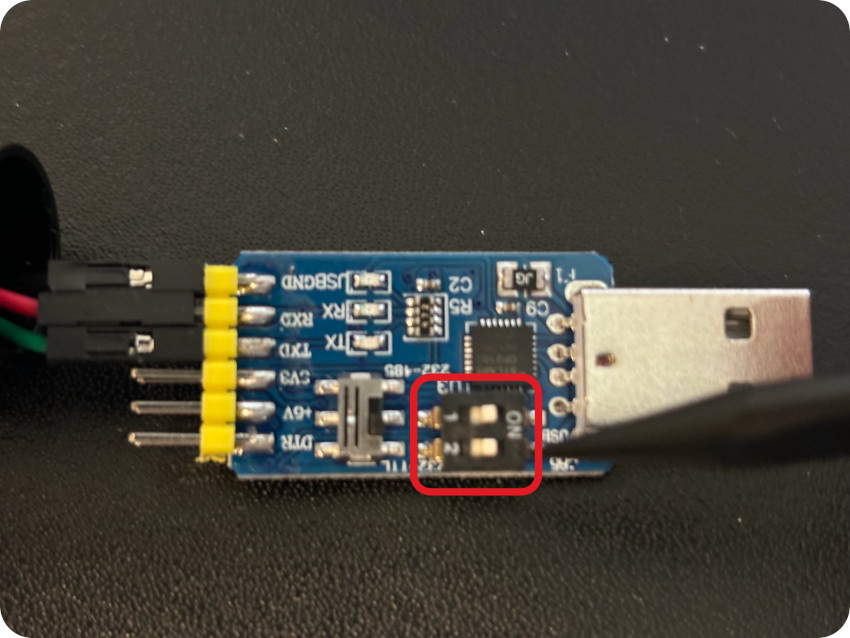
I could not find the documentation for this particular bridge … but, until then, It works fine with this configuration, at least from a GNU/Linux perspective. My guess is that these DIP switches are used to select the various supported modes (USB/TTL/232/485) of the bridge. Anyhow, I could finish and close the connector’s shell.
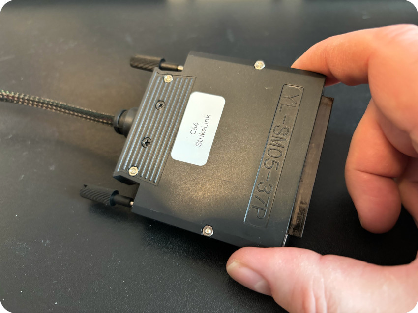
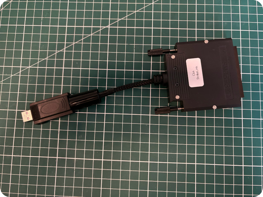
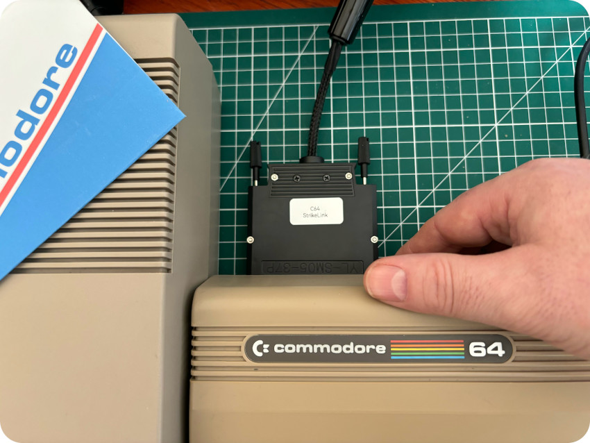
Here are a few pics of my weird ass-looking “StrikeLink” cable. It is some kind of “FrankenLink“, made from various bits, but I guess it is OK:
Let’s experiment and use the Commodore 64 as a dumb terminal (see here for more detail on dumb terminals and null modem communication).
On a personal note, I had the chance to get access to the Internet in the late 80’s early 90’s from universities networks, via dumb terminals, X-terminals or Unix workstations. As a particle physics student at IPN Lyon, I experienced the web for the first time from a dumb terminal, connected to a VM/CMS mainframe and, from there, accessed via a text-only browser the very first French web site (info.in2p3.fr), created and ran by the late Wojciech Wojcik on his NeXT cube at CC-IN2P3.
Here are the steps of my little experiment:
- I connected the C64 to the Raspberry Pi via the StrikeLink cable:
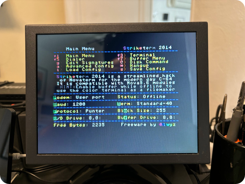
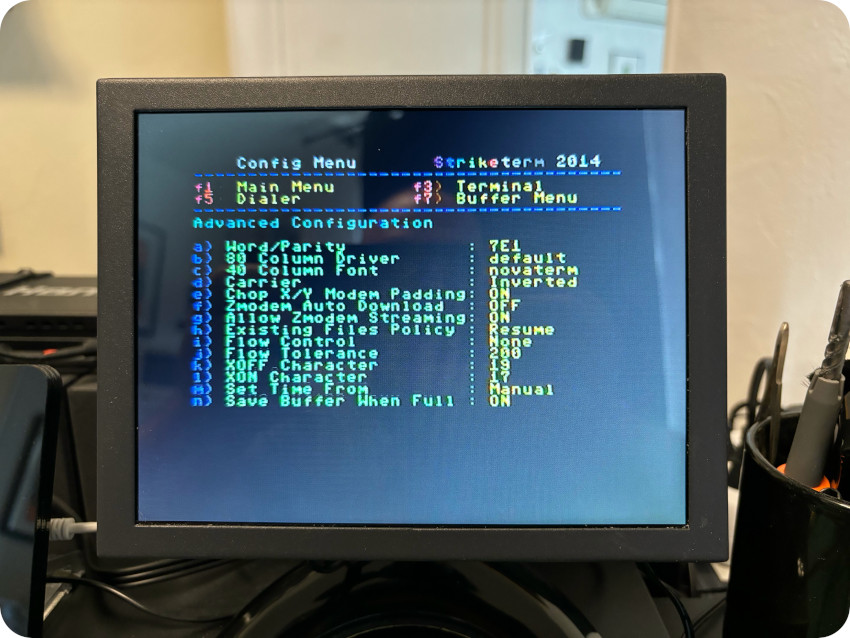
- On the C64, i ran the StrikeTerm (2014) terminal program and configured it this way:
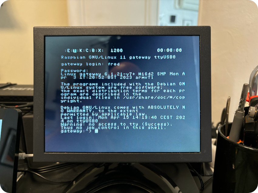
- On the Raspberry Pi, I ran this script (getty manages terminal connections – coming in, in this case, from /dev/ttyUSB0 – and prompts user with username and password in order to log into the system)
#!/bin/bash
while true
do
/sbin/getty -L 1200 ttyUSB0
done
And … there you go ! I was greeted by the usual GNU/Linux prompt and could log into the system from my C64:
Since I’m still a quantum nuts, I ran a Qiskit python script to create a three-qubit Greenberger–Horne–Zeilinger state. This is the script I wrote for fun when I used my Applie IIc as a dump terminal. It is very basic: it creates the quantum state and saves as a text file the corresponding quantum circuit. Here is the resulting output on the C64:
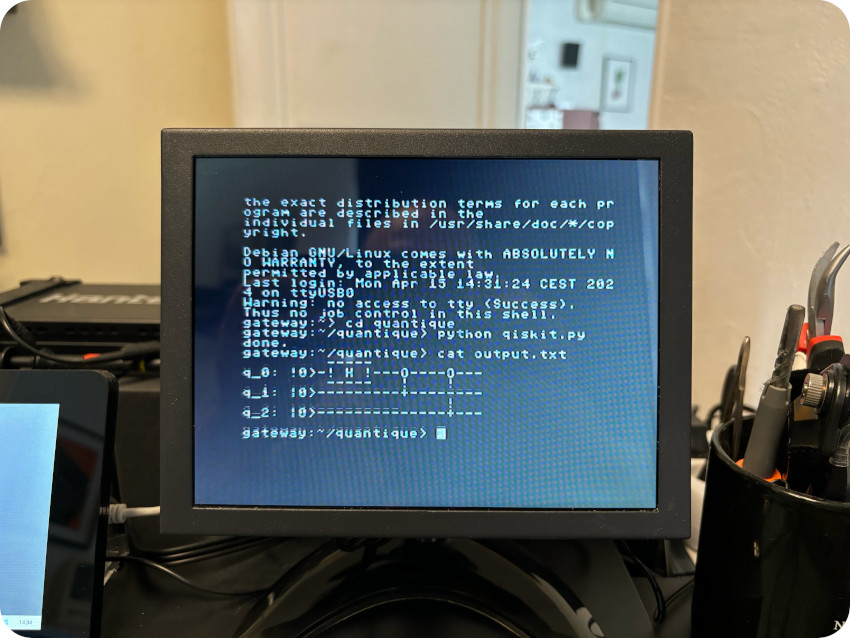
Future’s technology ran from a 40-years old tech. This is silly, but I love this !
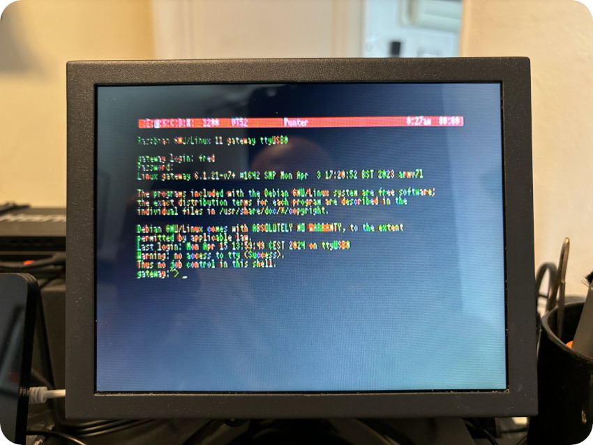
Note: I played with various Striketerm options, including the 80-column VT100 emulation mode. It works, but it is barely readable on my crappy LCD:
This is really cool ! But … let’s try something a bit different, and connect to BBS servers.
Bulletin Board Systems were computer servers users could connect to via a modem, and get access through a terminal to news, data, software, online games or message boards. They were used from the early 70’s up to the mid 90’s. As a kid, I never had the chance to use them. I actually bought my first modem (an Olitec 14 400) as a young adult in 1994, but for dial-up access to the Internet via the French ISP WorldNet.
In the 80’s, owning a modem and getting online as seen in the WarGames film or in the Whiz Kids TV series (that I loved to watch at the time) was a dream !
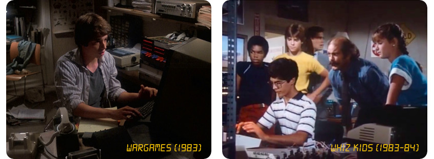
Of course, nowadays, land lines have changed so much that one cannot simply dial-in an old BBS. Thankfully, BBSes are still active and some can be accessed via telnet.
Let’s see how it goes. I browsed this BBS guide and chose to experiment with two BBSes:
- mutiny.cigdangle.com:65023: Why ? Because I’m currently binge watching the “Halt and Catch Fire” TV series and enjoying it very much. It is a fiction starring Lee Pace, Mackenzie Davis, Kerry Bishé, and Scoot McNairy. It depicts an insider’s view of the personal computer revolution from the 1980s up to the early 90’s. In season 2, the series focuses on a fictional startup called Mutiny running an online community of the same name.
The series stages a lot of vintage computers, and Mutiny is very much C64-centric, as pictured in the following shots:

[Halt and Catch Fire / (c) AMC]
The fictional Mutiny system of the TV series was inspired by PlayNet, a real life online service for C64’s that operated between 1984 and 1987. PlayNet system was licensed to Quantum Computer Services (and renamed Quantum Link), which became later … America Online. And Mutiny’s fictional online community look and feel was inspired by real world Clube Caribe / Habitat and Maniac Mansion from Lucasfilm Games.
There are a few BBSes named “Mutiny”, paying homage to “Halt and Catch Fire”. For a brief moment, let’s pretend it is the “real” (fictional) thing and have fun:
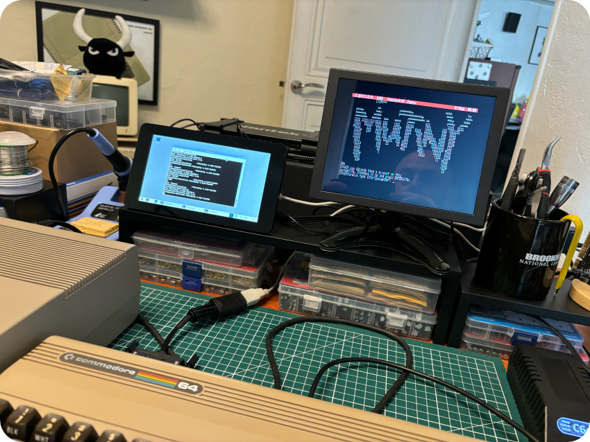
Oh well … this is a bit underwhelming. Indeed, most BBSes are not designed to be used on a C64, of course (though I thought a BBS called Mutiny would…). Therefore, they do not use PETSCII characters, and they look kind of bad on a C64. On modern terminals, these BBSes do actually look much better: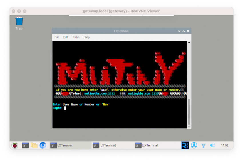
They do work on the C64 … but it is not glorious at all. Let’s do better !
- theoldnet.com:6400 : TheOldNet BBS is built on the work of PETSCII-BBS and allows users of C64 to browse the internet (stripping out all modern code to allow vintage computers to participate). This BBS is meant to be used on a “PETSCII” terminal and looks good on a C64. The “trick” to make it properly work with Striketerm is the following
-
- Configure Strikterm to use the “Standard-40” terminal mode
- On the gateway, start /sbin/getty the usual way
- On the C64, the GNU/Linux prompt will show up
- Log into the gateway as usual
- Type in “telnet theoldnet.com 6400” but DO NOT press enter yet
- Press C= + A on the C64. This is a feature of the “Standard-40” terminal mode, that toggles on/off PETSCII/ASCII conversion. By default, it is toggled on. It should be toggled off when using a Commodore-optimized BBS
- Press enter and … voilà !
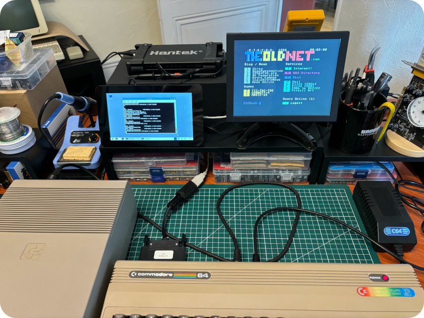
This is glorious ! Here are a few video captures:
| Loging into the gateway and accessing theoldnet.com BBS |
| From the BBS, browsing the web: |
WRAP UP
It’s been a long and interesting journey ! I started hunting for a C64 in November 2023 and finished this blog post in mid-April 2024. I learned so much during these months. At least … I feel less ignorant !
This was my longest and most challenging retro-computing project. Part because it involved working on a computer I technically knew almost nothing about beforehand. Part because I had to wait quite a bit (sometimes over a month) in between shipments of the various components I needed (from France, Poland, Spain, Italy, China). Part because, during these last months, I had been quite busy at work, including many business trips, meetings and conferences in Spain, Luxembourg, Norway and Germany. Exciting moments but … travels can be a bit tiring. So, when back in France, getting to know the Commodore 64 and its amazing community felt really nice and relaxing !
NEXT STEPS
I enjoyed so much my new Commodore 64 that … it feels now that I should spend quality time with my good old Amstrad CPC 464. It must a be jealous !
Indeed, it’s keyboard membrane needs a bit of care, and its enclosure is turning brittle. I am still hunting for an Amstrad DDI-1 drive, but, for some reasons, they are rare in France. And quite expensive !
I miss using CF2 3″ compact floppy disks. My wife’s father had an Amstrad CPC 6128 in the 80’s. He is so kind that he offered me a few years ago the disks he preciously preserved all this time. But I can’t use them and this drives me nuts !
Maybe I will opt for a DDI-5 if I can’t find a DDI-1 drive at a decent price.
In any case, i MUST celebrate the 40th birthday of the Amstrad CPC 464 (It was launched in April 1984 and I got mine in December 1984) !
ACKNOWLEDGMENTS, THANKS & LINKS
The Commodore 64 community is truly amazing and I would never have gone that far without its help.
Communities and dedicated web sites:
- System.cfg Forum (8bits topic): https://forum.system-cfg.com/viewforum.php?f=1 (French)
- Lemon64 Forum: https://www.lemon64.com
- The Pictorial C64 Fault Guide: https://www.pictorial64.com/
- Sven’s Techsite: http://tech.guitarsite.de/c64_scope.html
- Refurbished Commodore: https://refurbished-commodore.com/cpu-mos-6510
- C64 Wiki: https://www.c64-wiki.com/ and https://www.c64-wiki.de/ (German)
- Zimmers.net: https://www.zimmers.net/anonftp/pub/cbm/index.html
- MJK’s Commodore: https://ist.uwaterloo.ca/~schepers/MJK/c64.html
- World of Jani: https://blog.worldofjani.com/?cat=4
YouTubers:
- Adrian’s Digital Basement: https://www.youtube.com/c/adriansdigitalbasement, and more specifically
Note: Adrian is probably one of the most knowledgeable and nicest guy in the retro-computer community. He is now a full-time YouTuber, so, don’t hesitate and subscribe to his channel !
- Jan Beta: https://www.youtube.com/c/JanBeta, and more specifically
- Commodore 64 playlist
- The Retro Channel: https://www.youtube.com/@TheRetroChannel, and more specifically this didactic series
- Commodore 64 mania (French): https://www.youtube.com/@Commodore64mania/, and more specifically
- Retro bits: https://www.youtube.com/@retrobitstv
Manuals, Books & Schematics:
- Commodore 64 MicroComputer User Manual: http://www.zimmers.net/anonftp/pub/cbm/c64/manuals/C64_User_Manual_1984_2nd_Edition.pdf
- Commodore 64 Programmer’s Reference Guide: http://www.zimmers.net/anonftp/pub/cbm/c64/manuals/C64_Programmers_Reference_Guide.pdf
- Schematics: http://www.zimmers.net/anonftp/pub/cbm/schematics/computers/c64/index.html
- The Anatomy of the 1541 Disk Drive: http://www.bitsavers.org/pdf/commodore/The_Anatomy_of_the_1541_Disk_Drive_Jun84.pdf
- Single Drive Floppy Disk User’s Manual: https://www.commodore.ca/wp-content/uploads/2018/11/commodore_vic_1541_floppy_drive_users_manual.pdf
- Service Manual Model 1540/1541 Disk Drive: https://www.classic-computing.org/wp-content/uploads/2016/01/15401541_SERVICE-MANUAL.pdf
- Commodore 1541 Troubleshooting & Repair Guide: https://usermanual.wiki/Pdf/SAMSCommodore1541TroubleshootingRepairGuide.423279469/view
Bonjour Fred
What an adventure! I also have a C64 lying in the attic (next to an even older Atari 2600). I have no experience with this kind of repair, but reading your blog makes me want to get started one day. I’ll have to invest in some electronics equipment first though 😉
Thanks for documenting your process so well!
greetings and have fun,
Jan
Hi, this is Serene from PCBWay, whose businesses include PCB fabrication, 3D printing, etc.
It’s a pleasure to visit your website and read those articles about vintage computers. We wonder if you need any customized PCBs for any upgrades or repairs? PCBWay is willing to sponsor them by offering our prototyping services. Hope you share your feelings about ordering and your comments on the products in your posts.
Are you interested in the offer?
serene@pcbway.com
Dear Serene,
Thank you for reaching out, and thank you for your nice comment. I am actually already using PCBWay services! I recently created a small YouTube channel (https://www.youtube.com/@quantum-bits-org), and in the last video, I used PCBWay 3D-printing services: https://www.youtube.com/watch?v=6Q17MDr02uQ (around 27:00). The next video should be out by the end of next week, and it will be about building a mini-replica of a NeXT Cube computer. And … I also used PCBWay services for the enclosure 🙂 I’ll be happy to discuss with you !