After months of hard work restoring a Macintosh Plus, this time, I sailed towards more familiar shores: the Atari 1040STF. I owned an Atari 1040STF back in the late 80’s and I spent an enormous amount of time with it: learning software programming, using desktop publishing software, creating my first digital artworks…

I started working on the Mac Plus during #Marchintosh2022 … so I guess it made sense that I started working on an Atari device to celebrate Atari’s 50 years anniversary !
![]()
The Atari 1040STF
I have been using an Atari 1040STF from 1987 to 1990. It doesn’t seem like a lot of time, but I learned so much with it that it feels like a long story !
Atari was an easy choice (for me) at the time. I had pushed my beloved Amstrad CPC 464 to is limits. The 8-bit era was coming to an end, it was time to jump into the 16-bit era. The Macintosh Plus was a too expensive dream for me. The Amiga 1000 was very innovative, but also too pricey. The Amiga 500 wasn’t there yet (at least in France), and a strong community was nicely building up in Europe around the ST. So I opted for the “Jackintosh“:

I guess, during the 8-bit Amstrad CPC464 / Commodore 64 “war”, I was on Amstrad’s side. During the 16-bit Atari ST / Commodore Amiga “war” I was on Atari’s. Funny turn of events, since Shiraz Shivji’s design for the Atari ST is a descendant of the Commodore 64 design, and Jay Miner’s design for the Commodore Amiga is a descendant of Atari VCS and 8-bit computers designs. But let’s not create another war: the Amiga was an amazing piece of technology and is an important part of computer history.
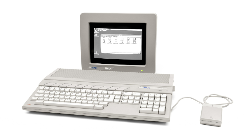 The Atari ST was my second computer. It is the machine on which I taught myself C, 68000 assembly language, event-based programming, GUI programming (GEM), and wrote tons of GFA Basic code. I had the SM124 high-resolution monochrome 640×400 bitmap display, so the ST could run “professional” software. I used it also for playing, of course, but not that much, since most games were only running with color monitors. Bolo was my favorite one.
This was the era of DTP (Desktop Publishing), and I used software like “Signum!”, “Publishing Partner” or “Calamus” to manage publications for my newly created Role Playing Games club (“Les Maîtres d’Arme “). These were the times of my first digital artworks (with “Degas Elite” and “Neochrome”). For these, I acquired for my first printers, starting with a Citizen 120D, and just a few years later, an HP Deskjet 500.
By mid-1990, I was 19 and I had been studying for a few years at Lyon’s University, focusing on mathematics and theoretical physics. I had started working part time – at first as a summer job, then, for around 3 years, 5-6 hours a week – as a research fellow at the École Centrale de Lyon, having access to Unix workstations (HP9000 series 300 / 400), as well as Motorola DSP 56000-based HP realtime signal acquisition systems. I needed a machine able to compile C, C++, run a Unix-like kernel, with X-Windows, a TCP/IP network stack. Although the Atari TT was intended to run Unix SVR4, it was too far away (1992) and too expensive.
It was the end of the road for my trusty Atari ST. I reluctantly jumped into the PC bandwagon, with an Intel 486DX33-based PC to run Turbo Pascal and Turbo C++. I had to live with MS-DOS and MS Windows for a while… Until mid-1994, where I ditched all this and happily switched to a Slackware GNU/Linux distribution (Kheops). The fun was back, full of kernel compilations, C programming, internet access, HTML learning, LaTeX typesetting, CERNLIB Fortan77 calculus, Maple V symbolic computing and PAW analysis for my PhD.
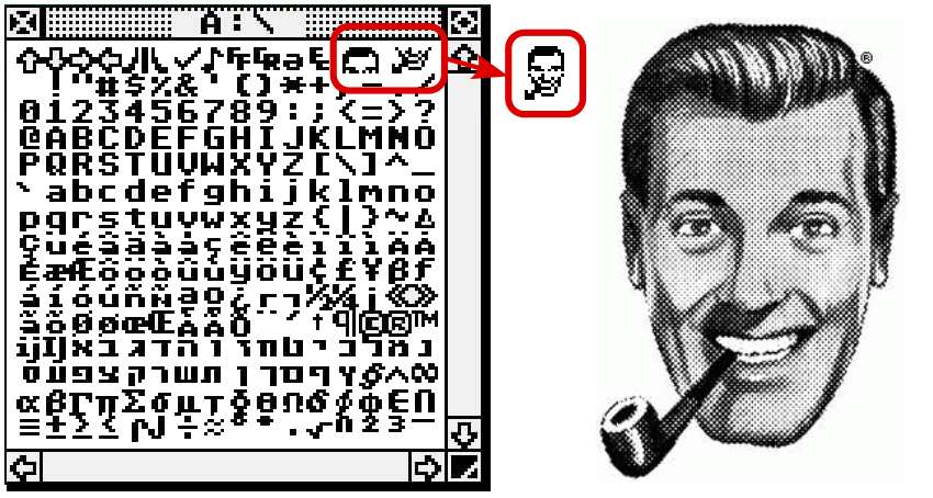
Fun fact: Slackware and Atari ST’s TOS are related through J.R. “Bob” Dobbs. The peculiar character set of the Atari ST includes four special chars (#28 to #31) recreating the iconic face of the Church of The SubGenius !
Sourcing an Atari STF
As I usually do, I went to LeBonCoin web site. I searched for an french AZERTY Atari 1040STF, without monitor, in the best possible conditions and that could be shipped home (and not picked up, since I don’t drive). After a few weeks, I opted for a nicely priced one (under 150€ including shipment), in very good conditions, but lacking mouse, power cord and video cable. I found a week later an Atari ST mouse, in good conditions, though slightly yellowed, for under 40€.
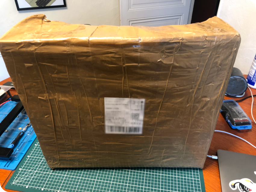
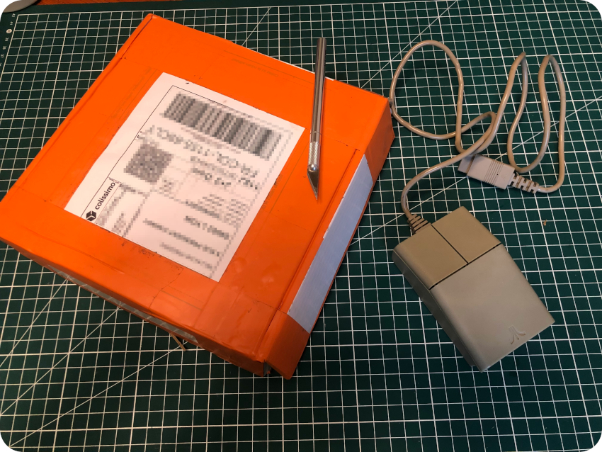
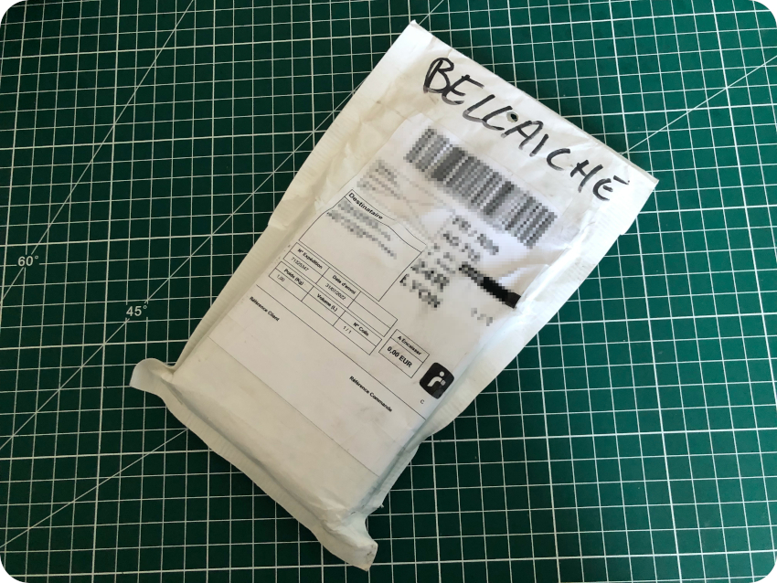
Just a few days later, I received this package, the device being secured inside with much bubble wrap and paper journals:
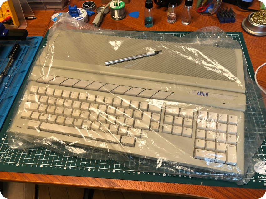
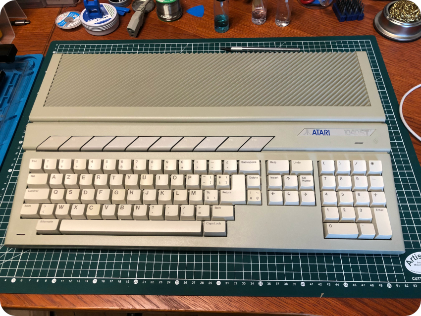
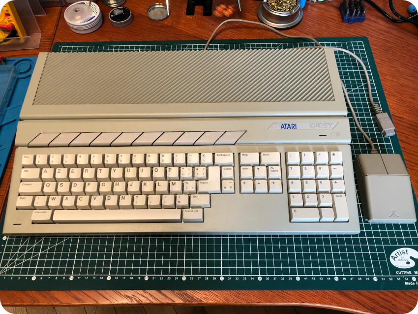
The Atari 1040STF itself was nicely wrapped and indeed in very good shape (… with a few surprises unmentioned in the offering, as you will see later):
I received the next week the mouse, slightly yellowed, as advertised:
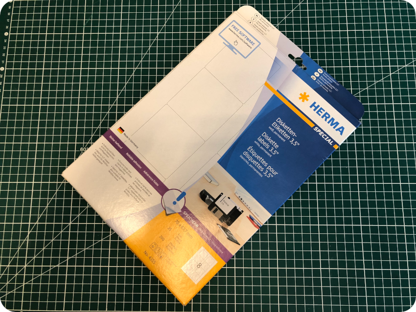
Joystick, diskettes, labels, USB floppy drive and video cables
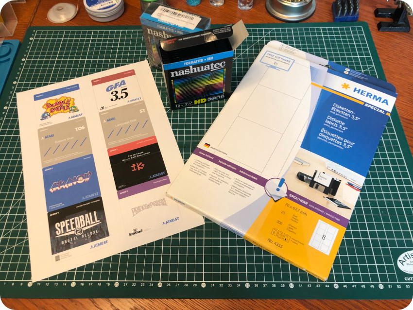
My goals for this Atari ST are – of course – to restore the device itself, but also to reproduce diskettes with old systems, applications and games. To complete theses goals, I had to complete this setup. I ordered on the Amazon:
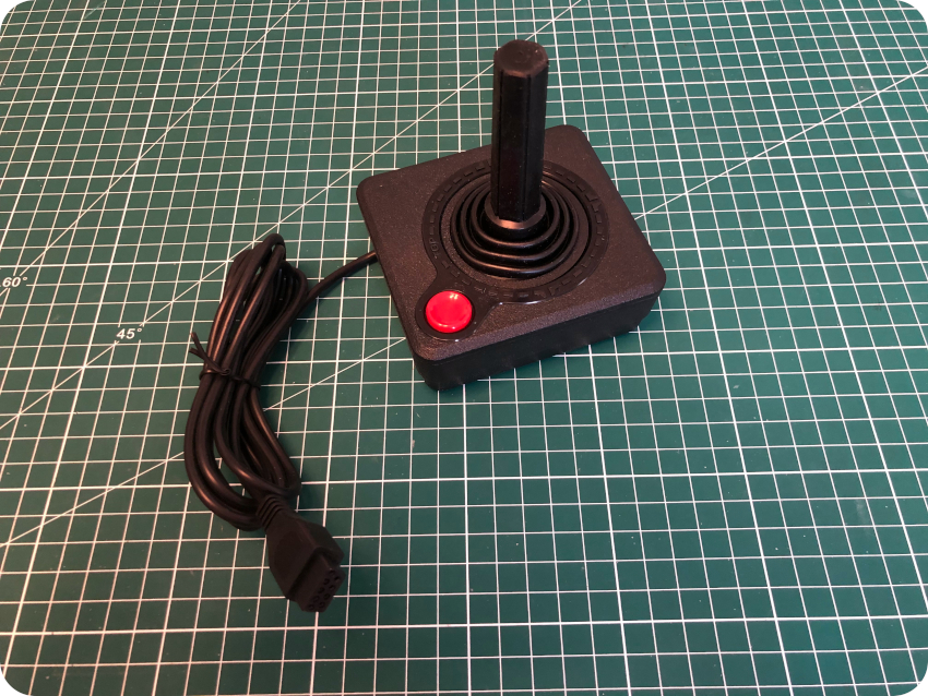
- An Atari CX40 joystick Chinese replica (which ergonomics is … as bad as I remembered. I guess I will search for a good old QuickShot II later on):
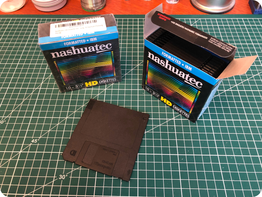
- Four packs of New Old Stock 3″1/2 HD diskettes (High Density / 1.44Mb) Nashuatec diskettes:
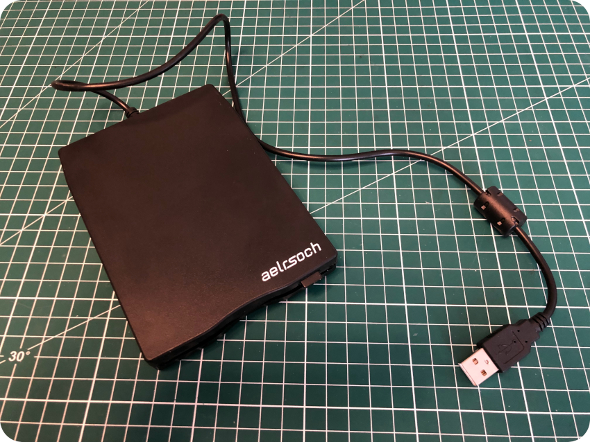
- An external USB 3″1/2 floppy disk drive (compatible with MacOS, GNU/Linux and MS-Windows):
- New Old Stock labels for 3″/12 diskettes:
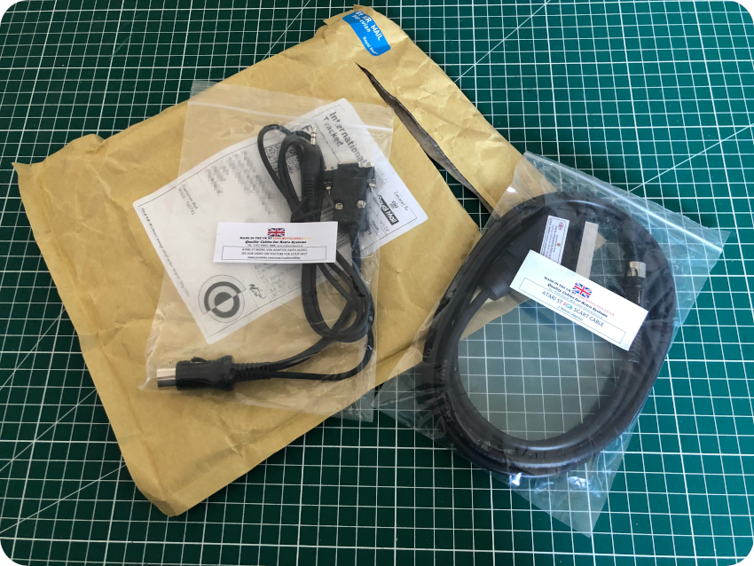
I also bought two video cables from coolnovelties.co.uk:
- Atari ST RGB SCART cable (for 320×200 and 640×200 color modes)
- Atari ST Mono VGA Adapter (for the 640×400 monochrome mode)
To finish the purchases, I found on LeBonCoin a set of 7 DD (Double Density / 720kB) diskettes (for 10 €, but unknown conditions). I received them a few days after the ST:
Unboxing the Atari ST … and a few surprises !
I removed the plastic wrap protecting the Atari ST. It was indeed in almost perfect conditions. No scratches, no yellowing, no stain, no unpleasant smell. Nice !
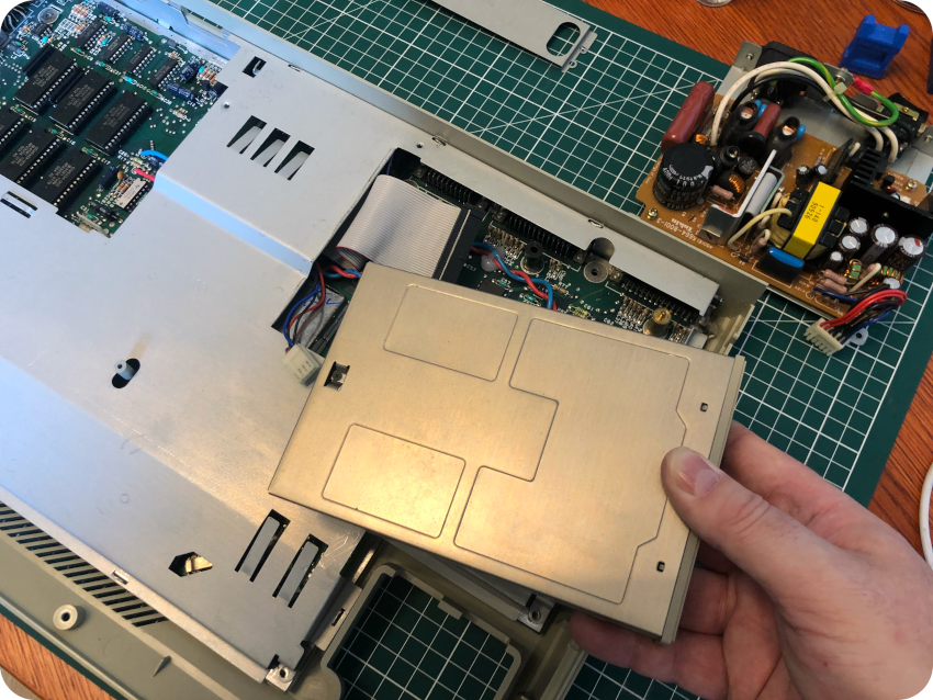
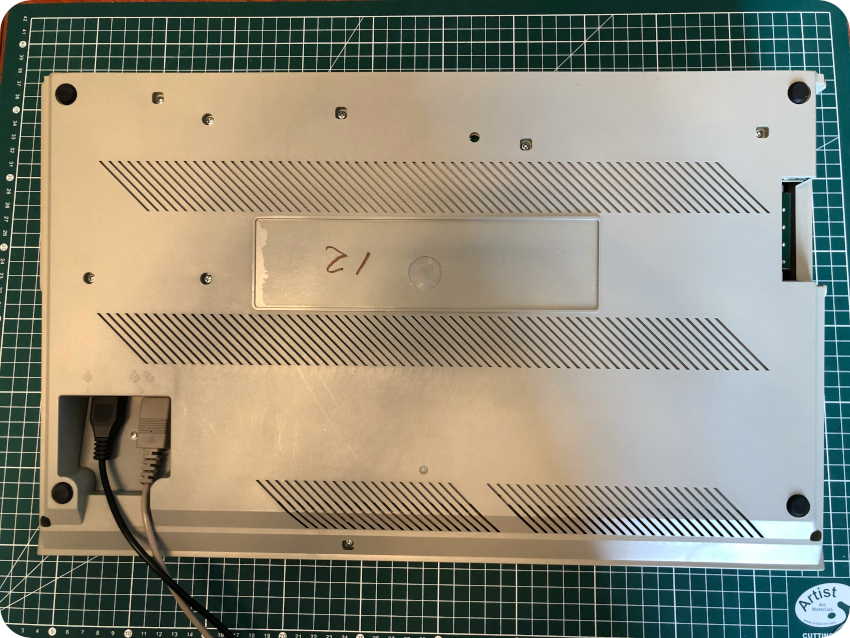
Then, I flipped it to inspect the internal floppy drive:
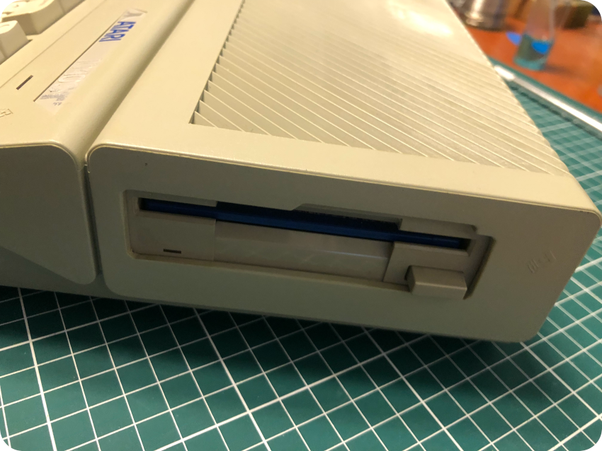
Now, that was a surprise !
- The internal floppy disk drive was replaced by what looks like a non Atari ST drive. The bezels of Atari ST drives are indeed different from standard ones. Atari drives bezels have the “slanted” ST look (with the eject button either in the middle or on the right side) whereas bezels of standard drives have a “straight” look :
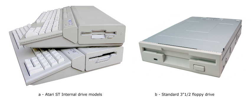
- The case was cut to accommodate room for a different drive. Even though this mod was not described in the offering (and I would have preferred a unaltered Atari ST), the cut was almost professionally done. From the look of the cut, the replaced drive was one with a middle eject button.
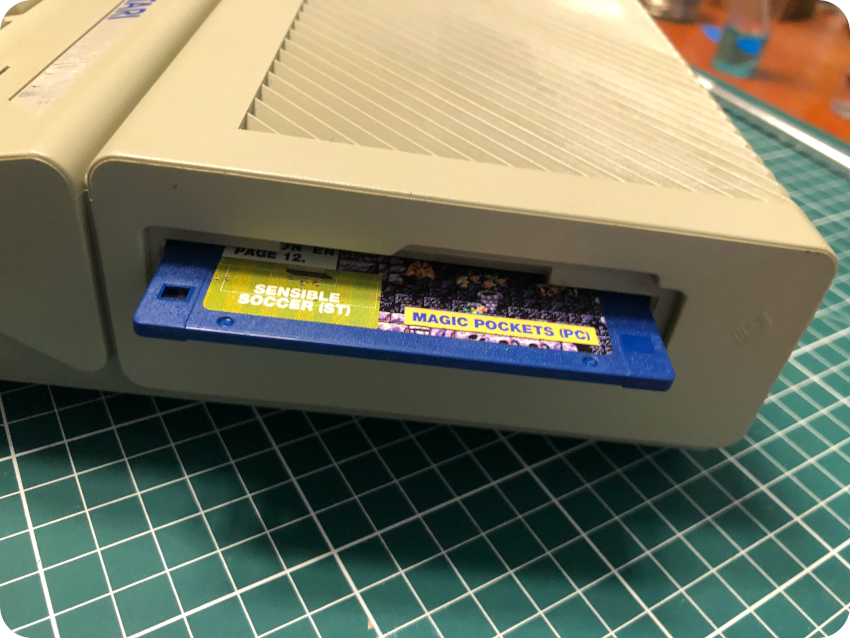
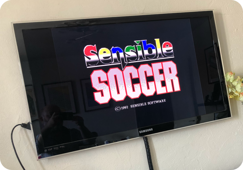
- A diskette was left into the drive. I could eject it without problems (though it felt like the mechanical parts would need a bit of lithium white grease). The diskette is a demo version of a soccer game (“Sensible Soccer”), from a old French magazine (Génération 4). I have no words to express how much I hate sports, and soccer in particular … but this was somehow a win: I had not yet received the 7 double density diskettes from LeBonCoin, and this demo diskette would allow me to test the drive and the Atari ST right away !
With this in mind, I flipped the ST to inspect the back of the enclosure and the connectors … and I was up for another surprise:
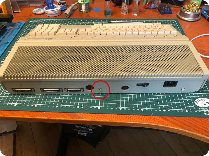
Another modification was there: a switch had been added, on the back of the Atari. I figured it might be related to the internal floppy disk drive mod. I contacted the seller on LeBonCoin’s chat. He claimed he had no idea what these mods were for. These mods appear to be very nicely done. If he actually were the author of these, I guess I would have been proud of them and would have told me. Or maybe he was afraid I would cancel the deal. Who knows ?
I had not yet received the video cables. But I wanted to make sure right away if there were something fishy or not. I had so much troubles with the Mac Plus internal floppy disk drive, I had to make sure the ST internal drive worked !
I plugged a standard power cord I had in stock, inserted the demo disk and powered the Atari ST on. No magic smoke. The power LED went on and the Atari started reading the diskette. LED drive activity. No weird noises, the drive kept on reading the disk until (I guess) the game started (I would not know without video cable).
Then I turned off the Atari ST, pushed the switch in the second position, and powered back the ST. This time, the ST still powered on, but would not seek the floppy disk. I powered the ST off, push the switch back to its original position, powered back … and, from the sound of it, the ST booted from the internal floppy drive.
At this stage, I concluded that this mod was probably an A/B switch. Without mod, an Atari ST only boots from the internal A drive and cannot boot from an external B drive. Once implemented, an A/B switch mod provides a switch that swaps the drive select signals, allowing the ability to toggle Drive A between the internal and external unit.
A few days later, the video cables arrived. I did the same tests, but this time with video feedback:
- On position A, the Atari booted from the internal drive, and started the Soccer game. Good (well … if you like soccer)
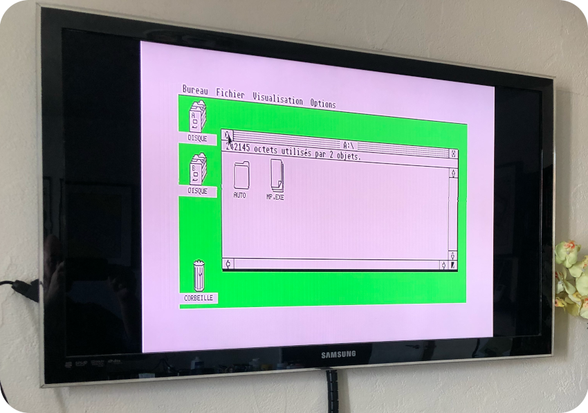
- On position B, the Atari did not seem to be seeking the internal drive. No noise. No LED activity. After around 20-30 seconds, it launched the GEM desktop (as an Atari ST always does whenever no disks are inserted). Was it trying to boot from the external one ? Since I do not have an external drive, it is difficult to draw definite conclusions at this stage…
Anyways, apart from these mods, this Atari is in almost perfect conditions and works. The replaced drive works also nicely. I thus kept it as is and validated the deal.
Now, let’s open this bad boy and see what is really going on !
Opening Up
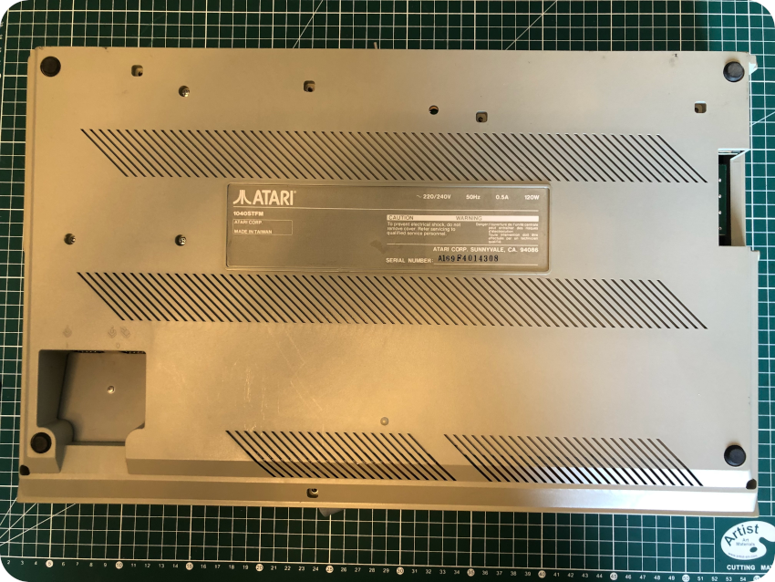
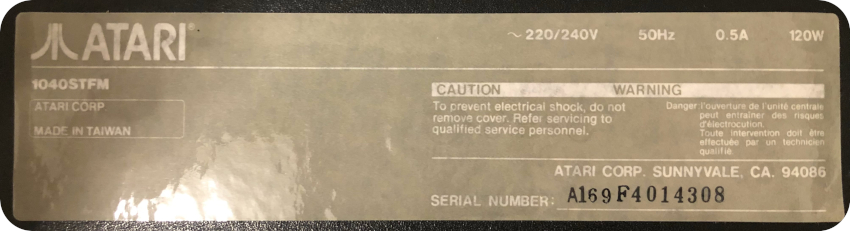
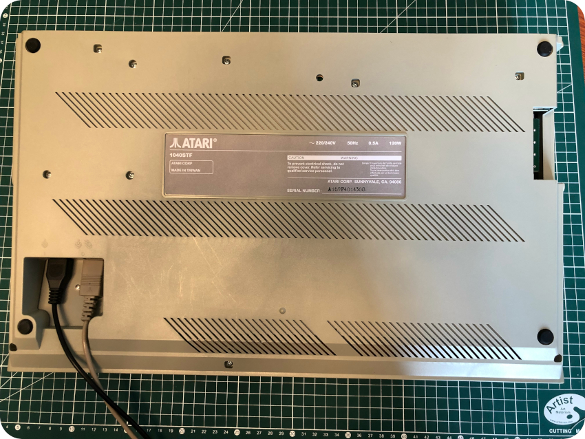
To open up the Atari 1040ST, one has to flip it, the keyboard facing down. And … here comes another surprise: the sticker on the bottom says this Atari is … a 1040STFM. Which clearly it is not, since STFMs are STs with a RF Modulator… and this ST has no modulator output.
Was the bottom part of this Atari 1040ST taken from an Atari 1040SFM ? Is this a misprint on the sticker ? I could not find any complete serial number database or serial number decoder, so it is really hard to say. Yet another mystery…
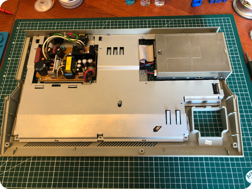
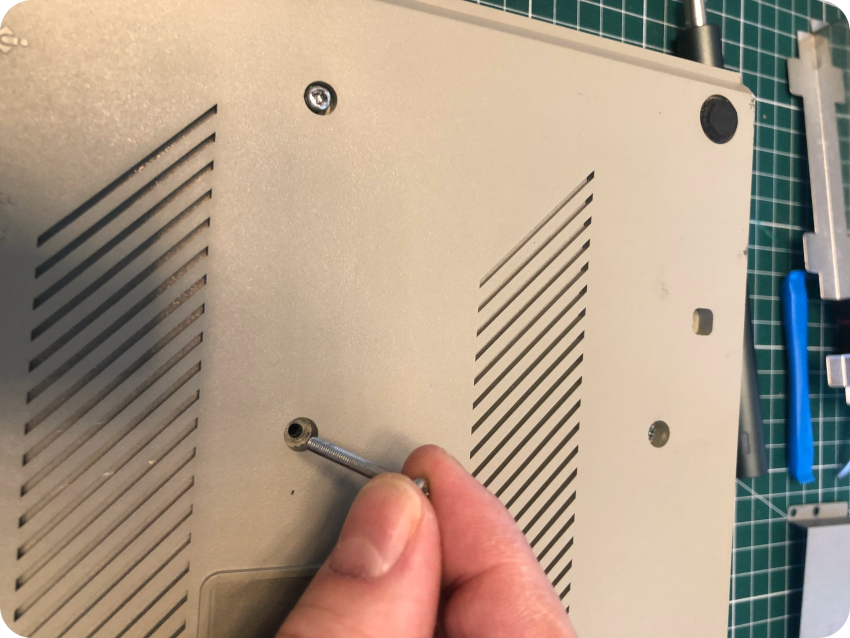
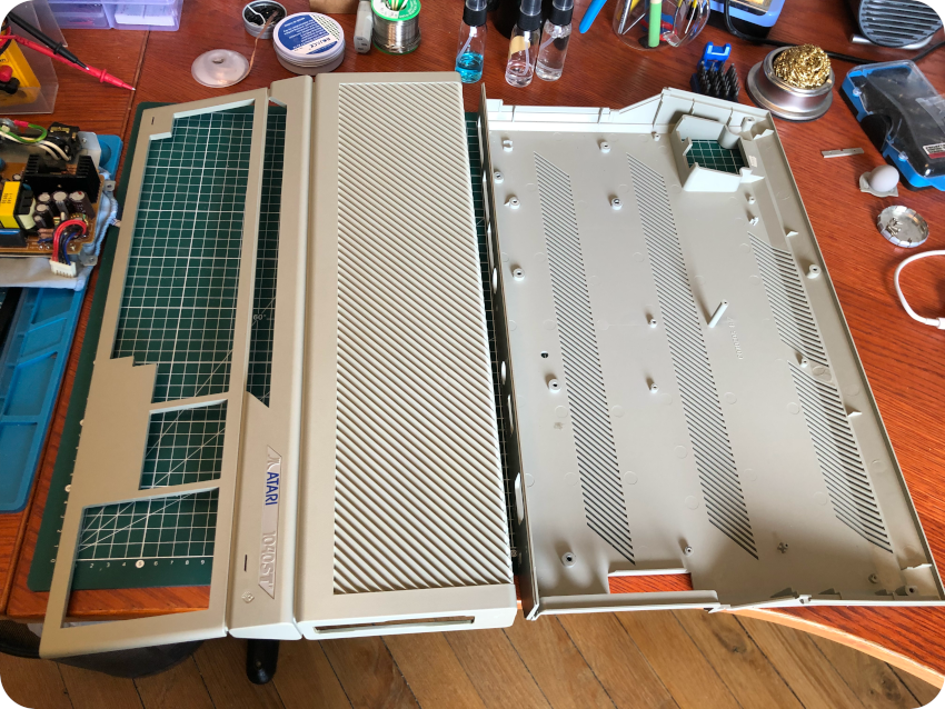
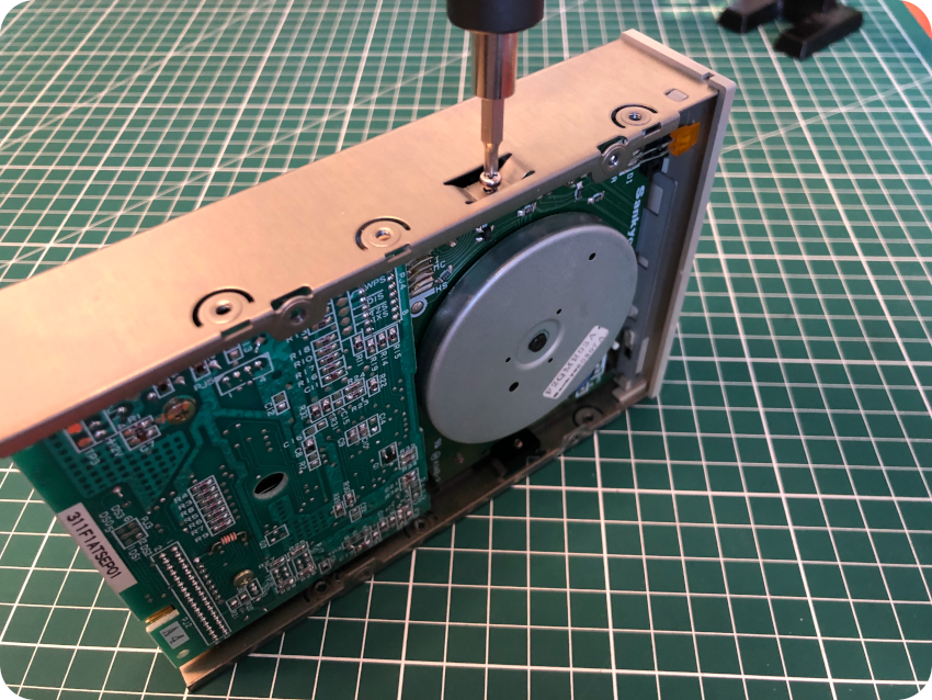
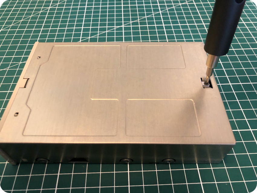
Let’s dig in. I removed the bottom case screws (square holes), leaving for now the screws holding the floppy disk (round holes):
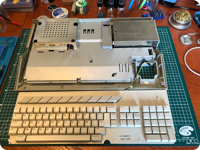
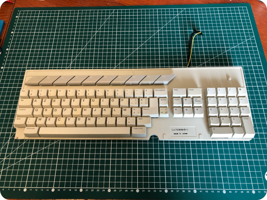
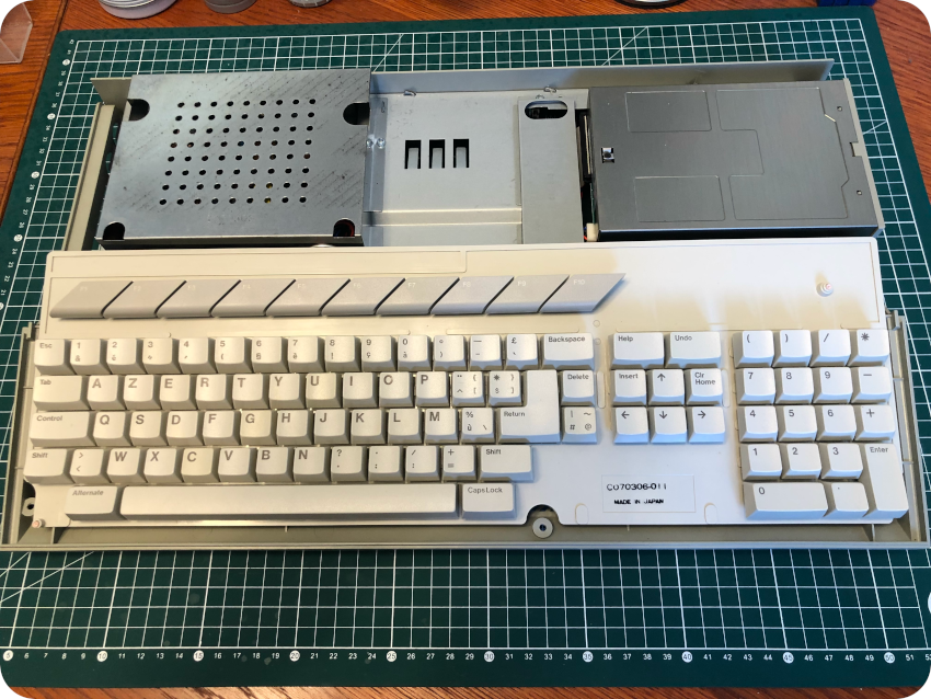
Once removed, I flipped back the case, and removed the top bezel:
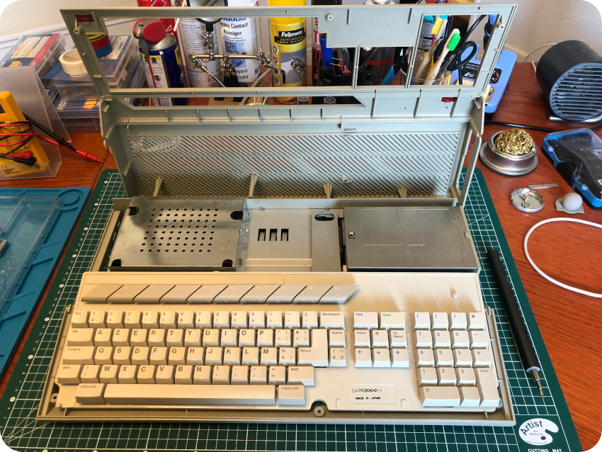
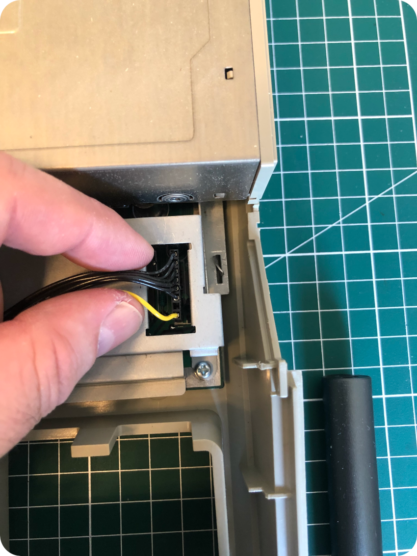
The keyboard is not screwed, and just sits on top the main metal shield. Once the keyboard is taken apart, it is easy to unplug its connector:
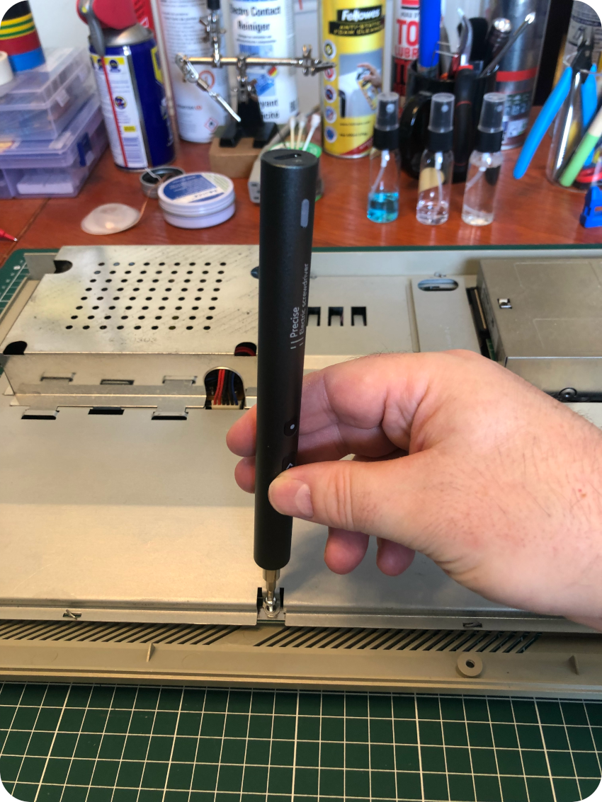
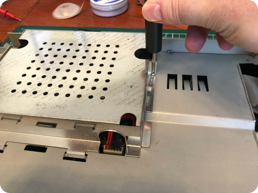
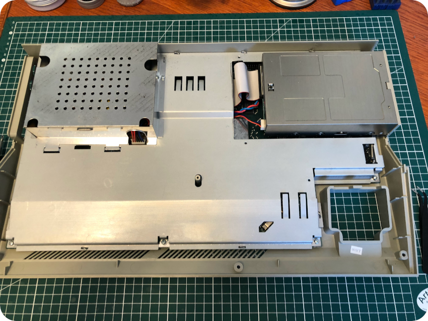
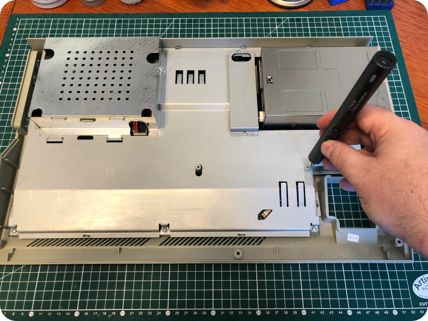
The keyboard is now free. Now, it is time to remove all these metal shields. First, I removed the screws from the main shield:
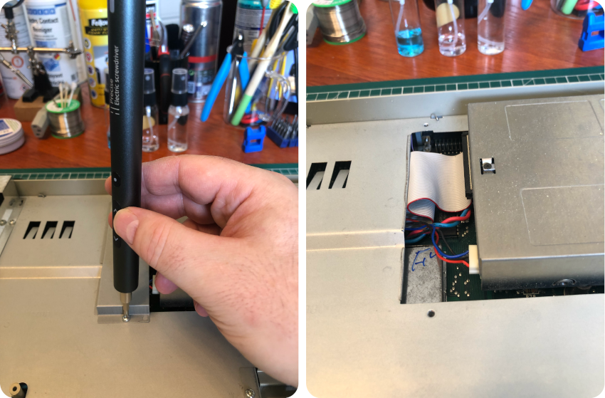
Then, I removed the ones from the shield near the floppy disk drive:
I unscrewed the shield protecting the internal power supply …
To remove this protective shield, one also have to untwist this metal tab:
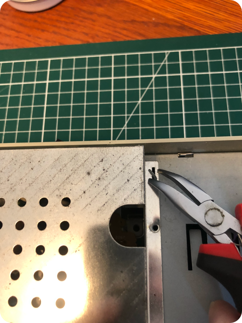
Once done, I unscrewed the little shield close to the keyboard connector:
There you go, these three small metal shields are freed:
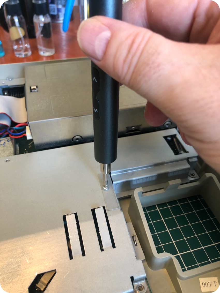
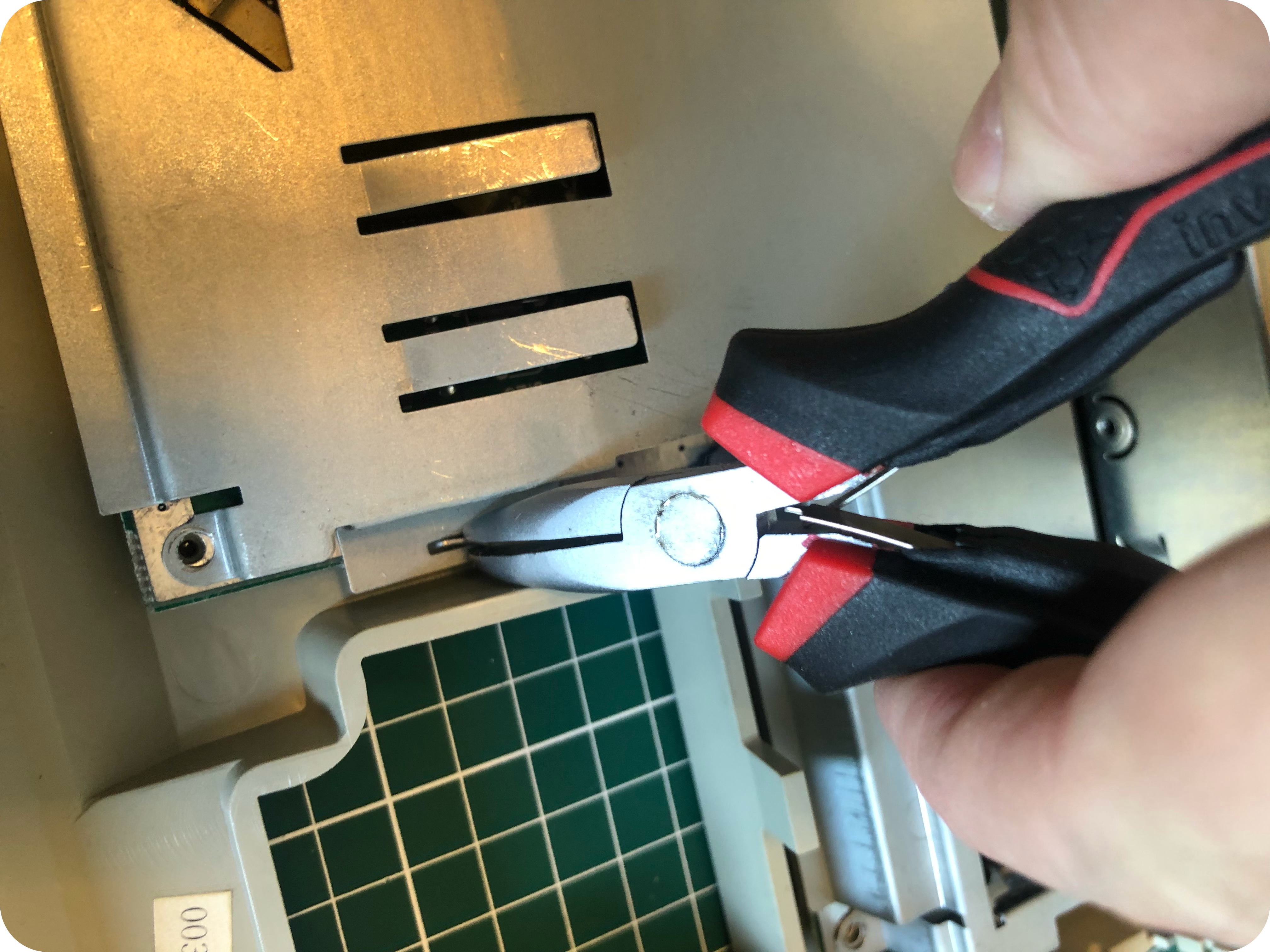
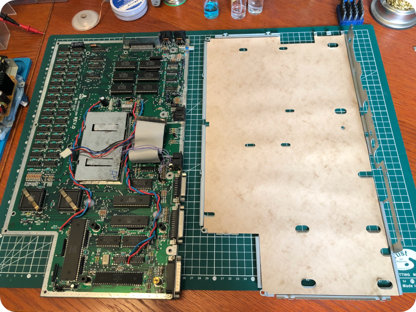
I flipped once again the device, to remove the screws holding the floppy disk drive:
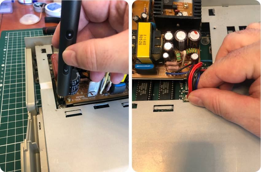
Then I unscrewed the power supply and disconnected its plug:
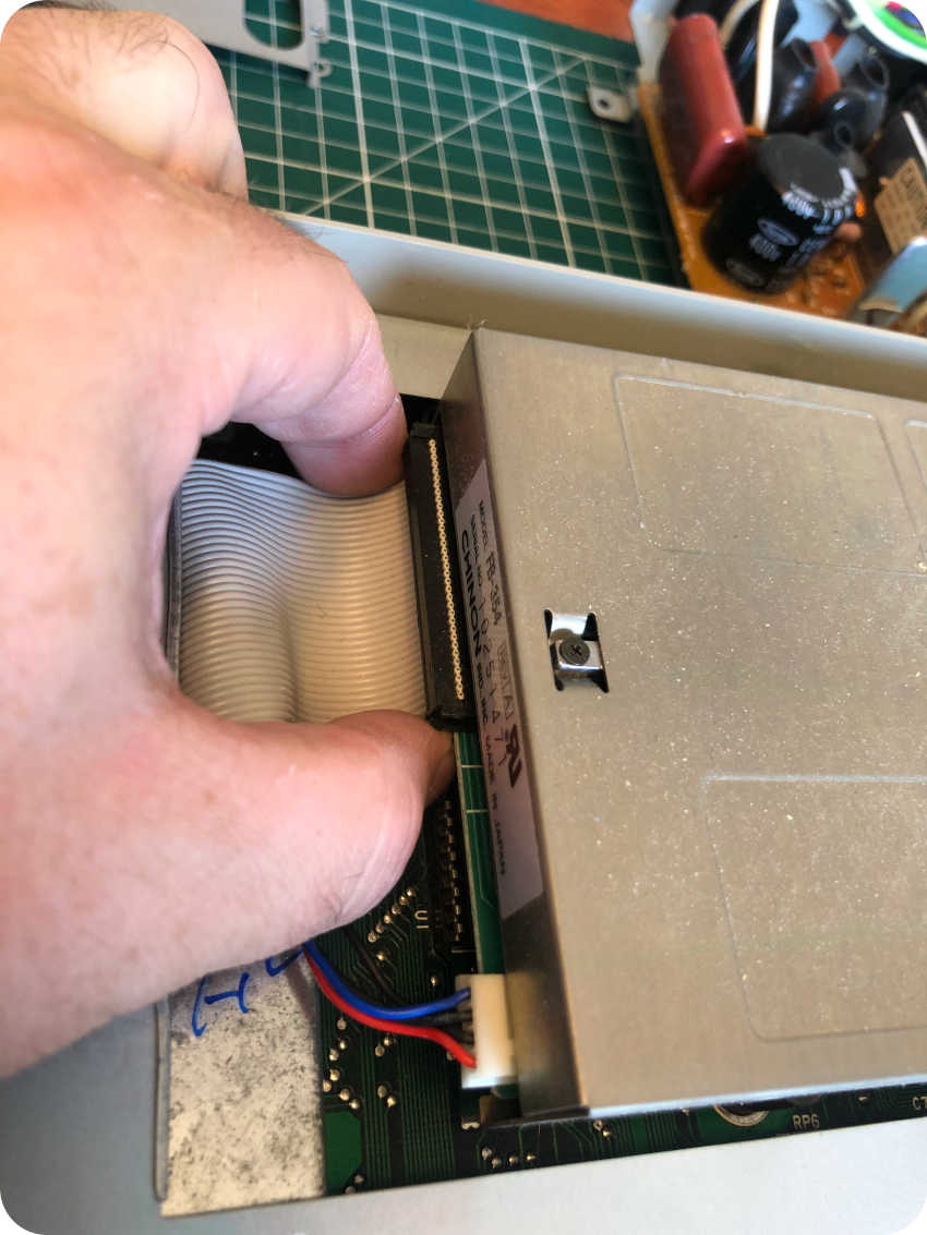
Then I disconnected the floppy disk drive ribbon and removed the drive itself:
Once done, the main metal shield can be removed, untwisting all its tabs:
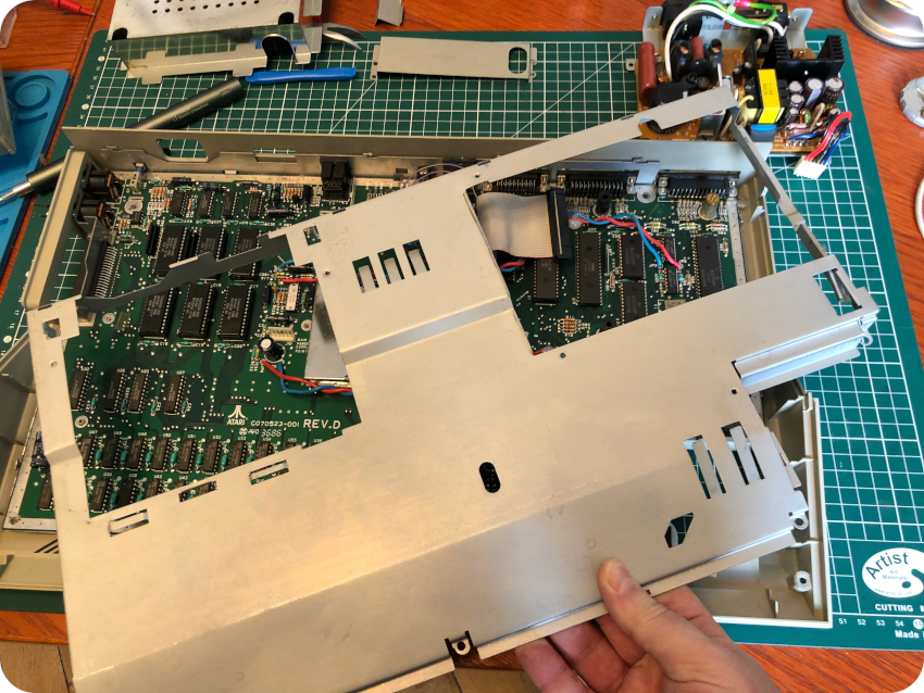
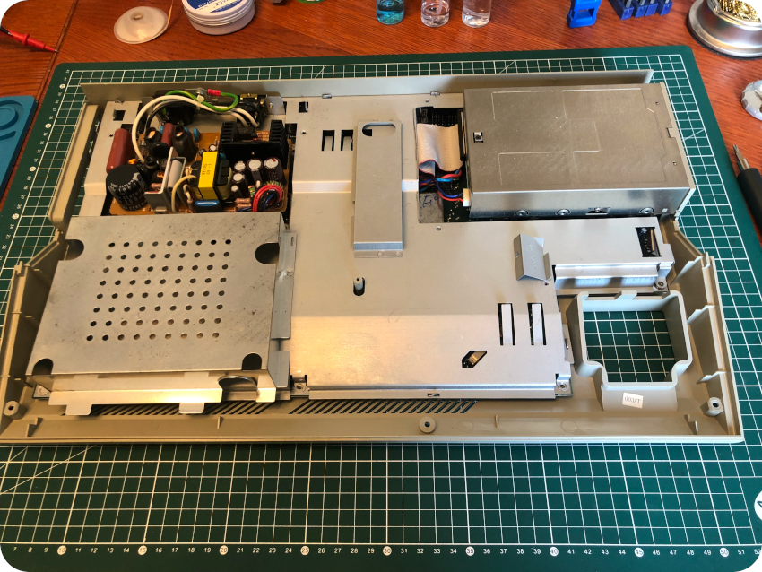
All the top metal shields are now removed:
To remove the PCB from the case, I had first to unscrew the added switch:
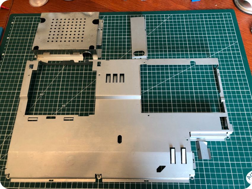
The last step was to remove the bottom insulation shield:
As expected, there is no RF modulator on the main PCB, confirming (if needed) that this is not an Atari 1040 STFM but indeed and Atari 1040 STF.
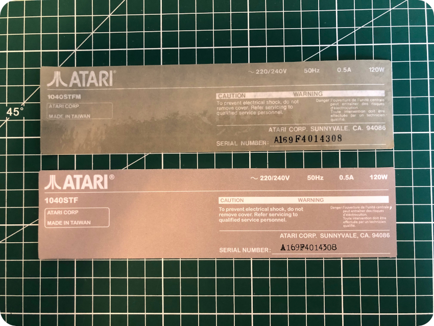
The sticker on the top bezel (1040STF) is thus correct, while the one on the bottom (1040STFM) is not: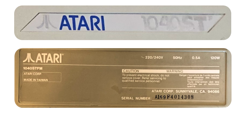
It might not be such an usual thing. Googling around, I could find at least one other 1040STF model with a 1040STFM stickers on its back…
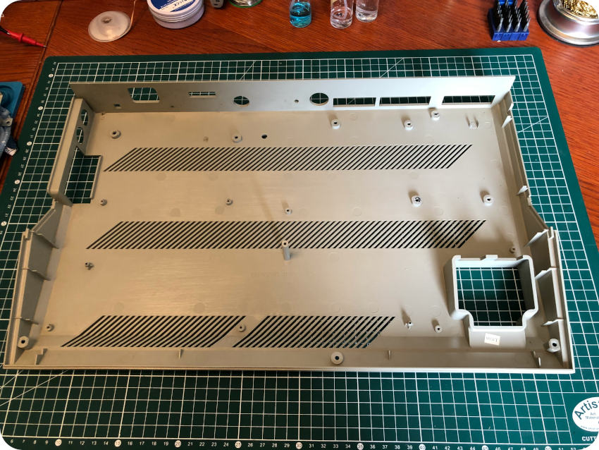
Cleaning the case
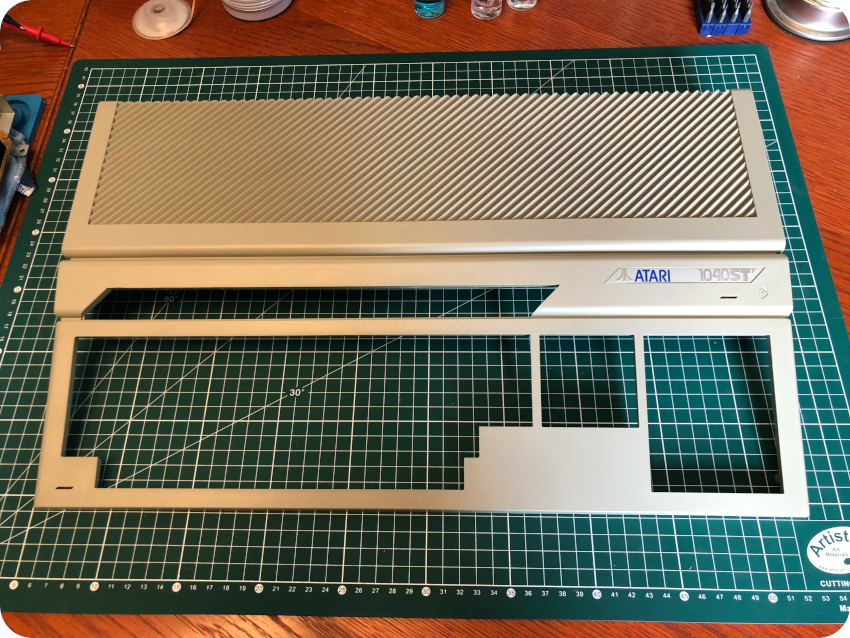
Before cleaning up the case, I carefully removed the sticker to keep it safe, in order to replace it later with a new one, with the proper “1040STF” label. The case itself is in very good condition: rather clean, no scratches or cracks:
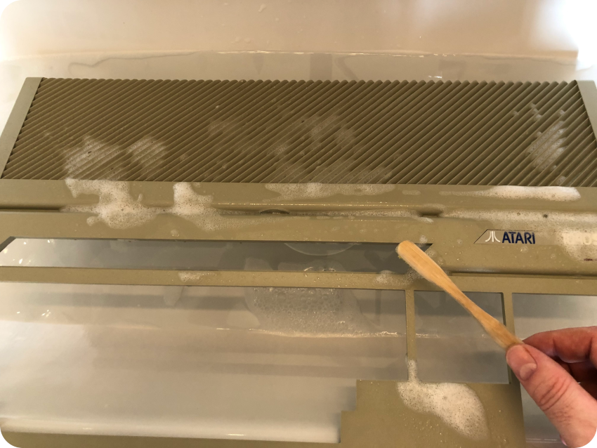
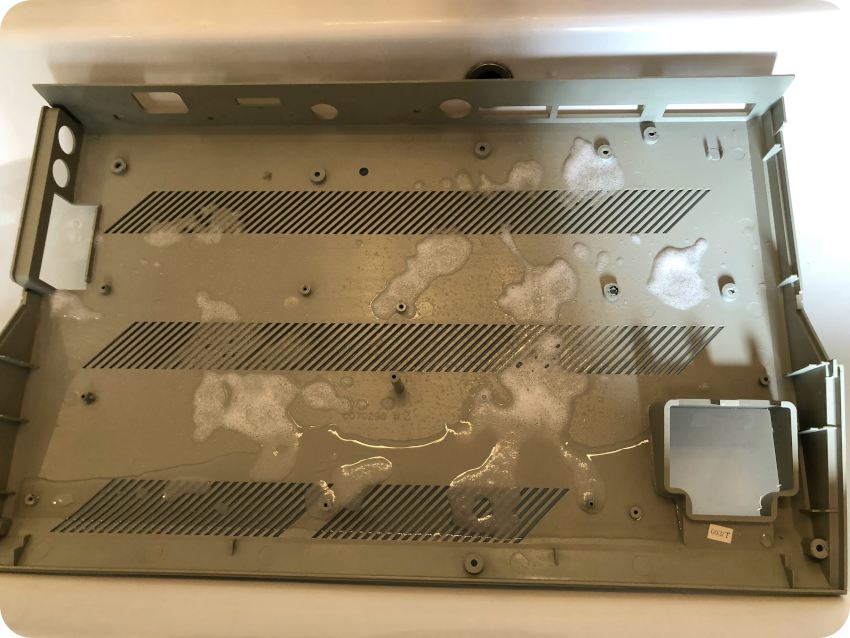
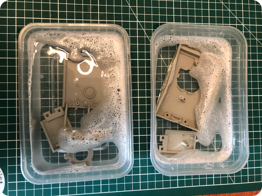
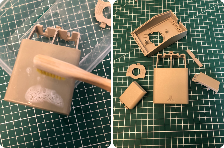
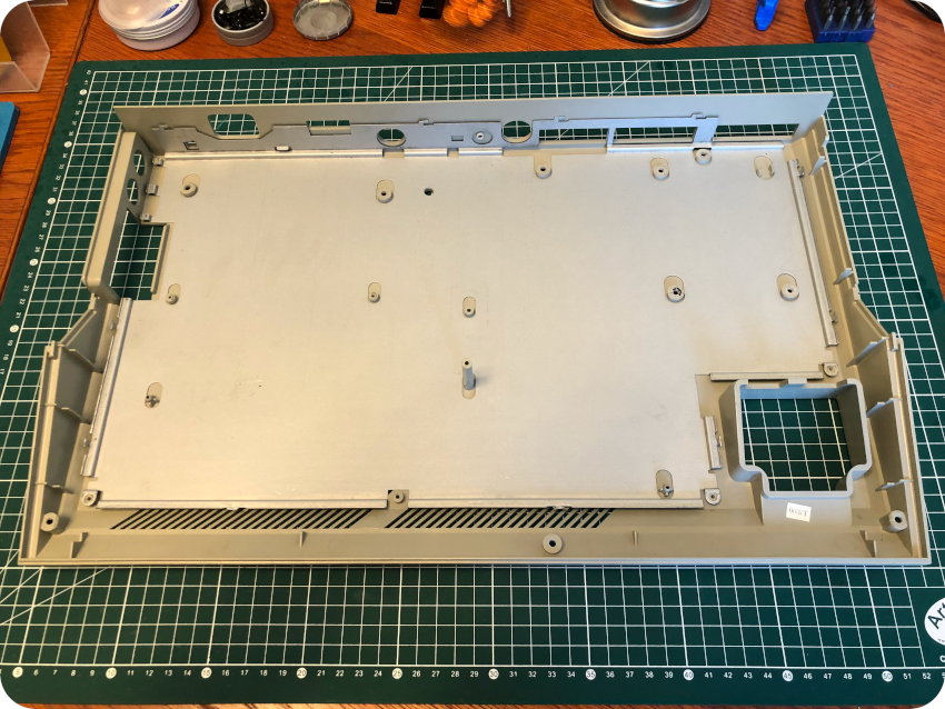
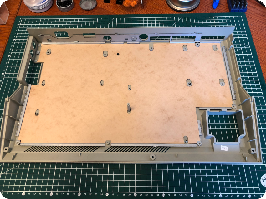
Nevertheless, I followed my usual cleaning routine (soapy water, toothbrush and elbow grease), starting with the top part:
I did the same with the bottom part, after it’s been vacuumed:
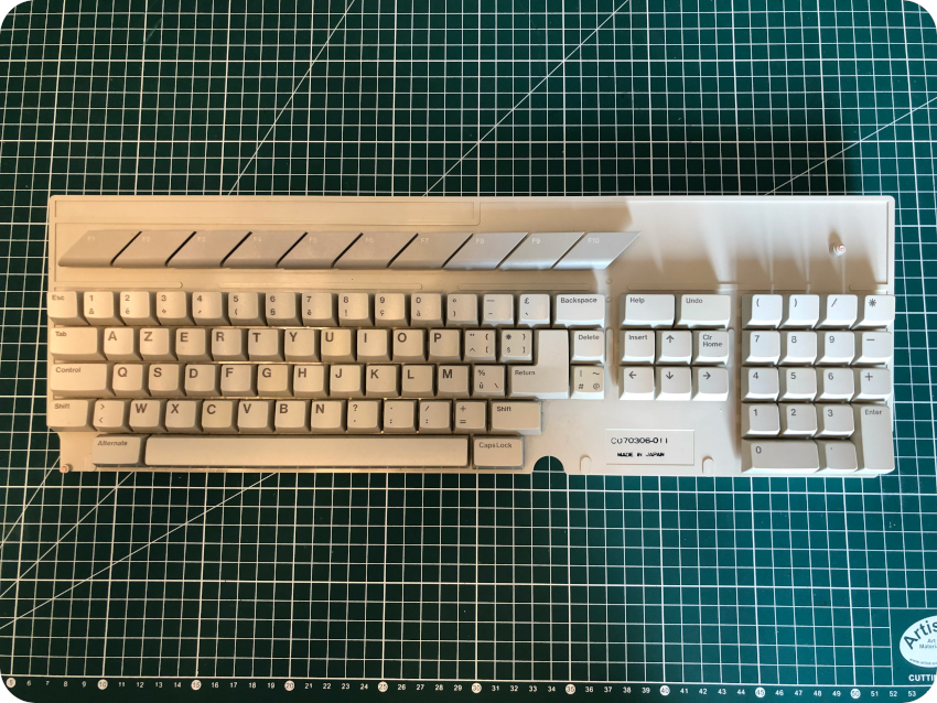
Cleaning the keyboard
While the enclosure was drying, I took care of the keyboard:
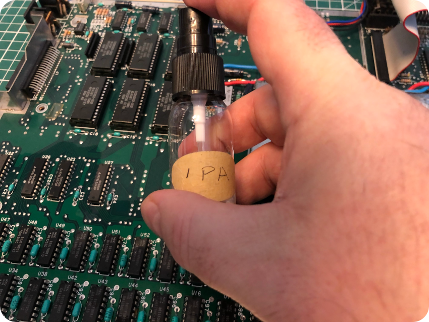
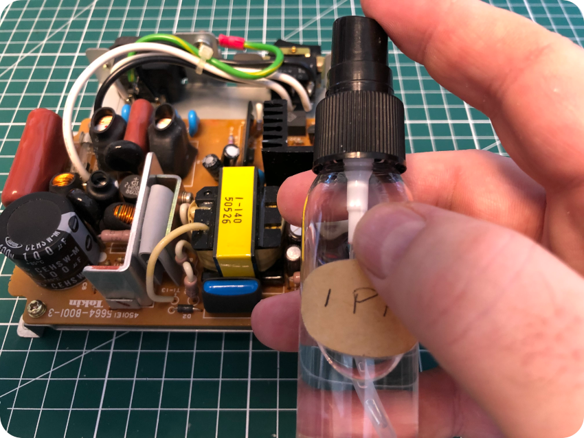
I started by cleaning the bottom part with IPA:
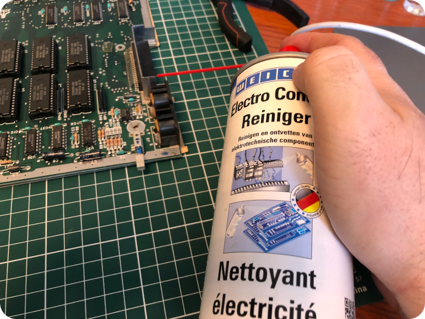
Then I took care of the Mouse / Joystick connectors. Oh boy, I did not remember this was such bad place for these. This is so annoying ! It would have been so much practical to plug / unplug these devices had the connectors been placed on the side of the ST. Costs reduction I guess. Anyway, I took care of them with contact cleaner:
Then I put on a bit of Kapton tape where needed:
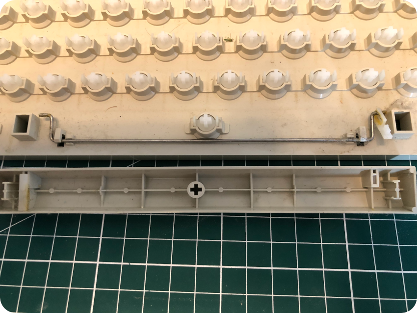
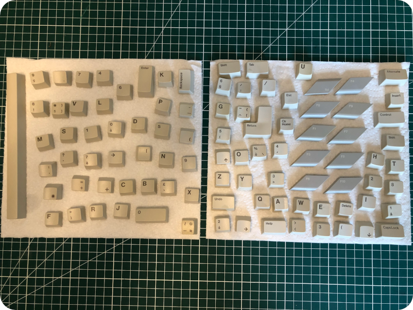
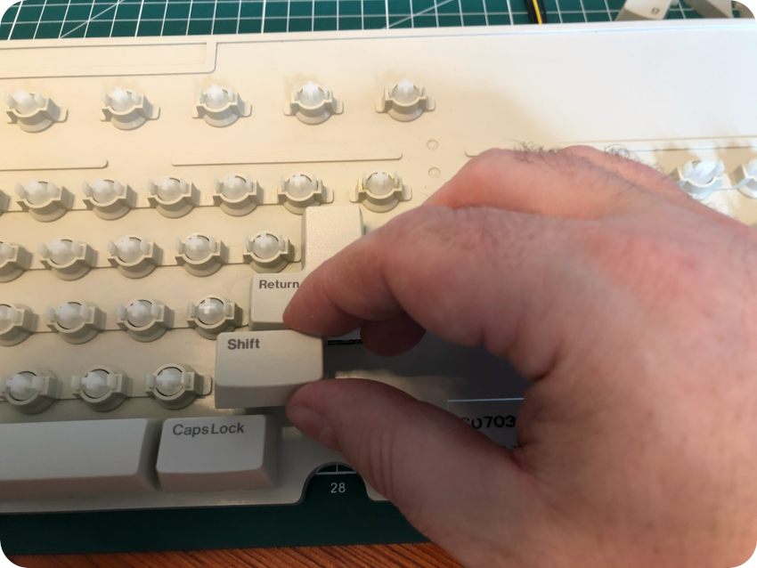
Then I started to pull out the keys one by one:
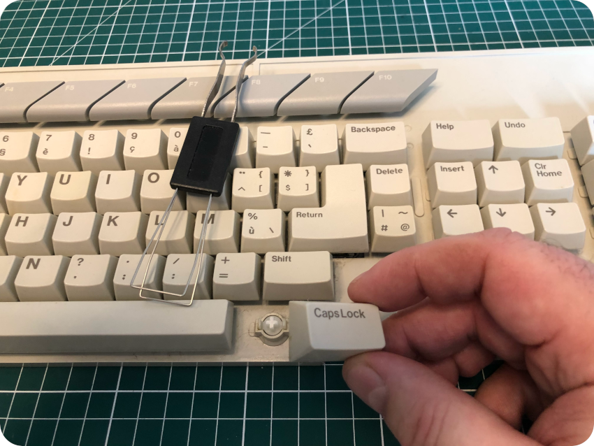
A small piece of plastic snapped while I removed the space bar. Nothing too bad, it will easily be glued back:
Just like the enclosure, the keyboard is in very good condition. Of course, it has a little amount of hair and dust bunnies:
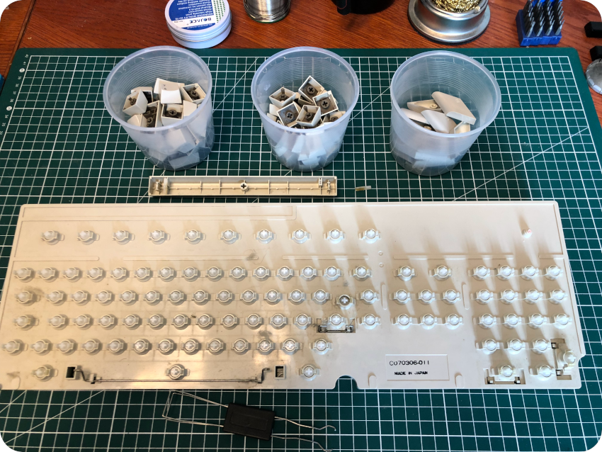
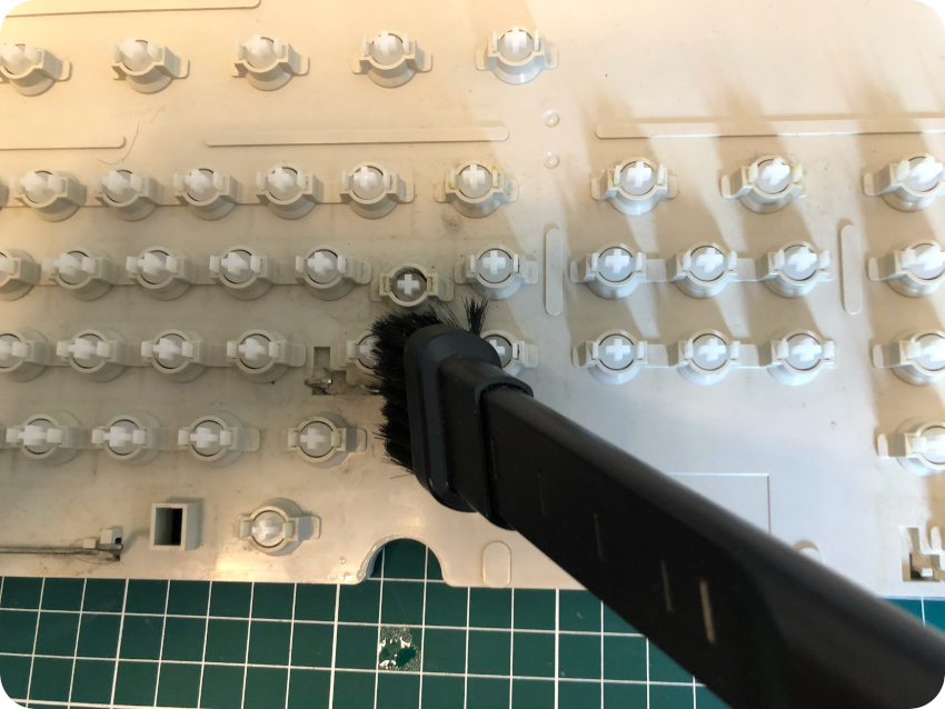
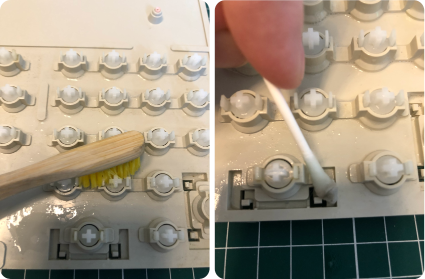
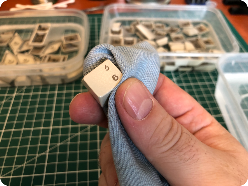
I vacuumed it, then cleaned it with soapy water, a soft toothbrush, cotton swabs, then IPA and a micro-fiber cloth:
I let the keys soak into warm soapy water for a few hours, then cleaned them one by one with a cloth:
I let the keys dry:
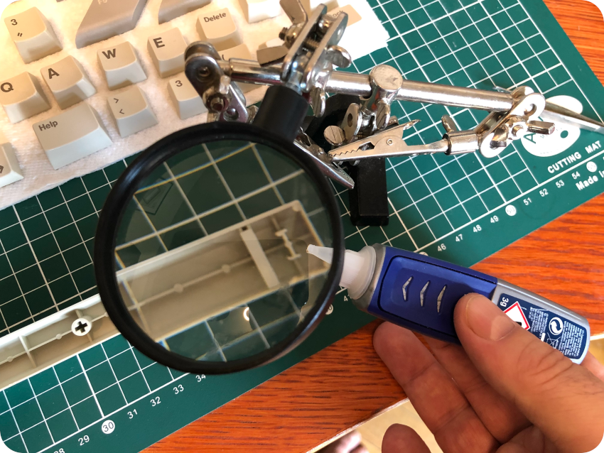
Meanwhile, I took care of the snapped plastic piece from the space bar, with superglue:
And I put back each key:
There you go, a cleaned and freshly smelling keyboard:
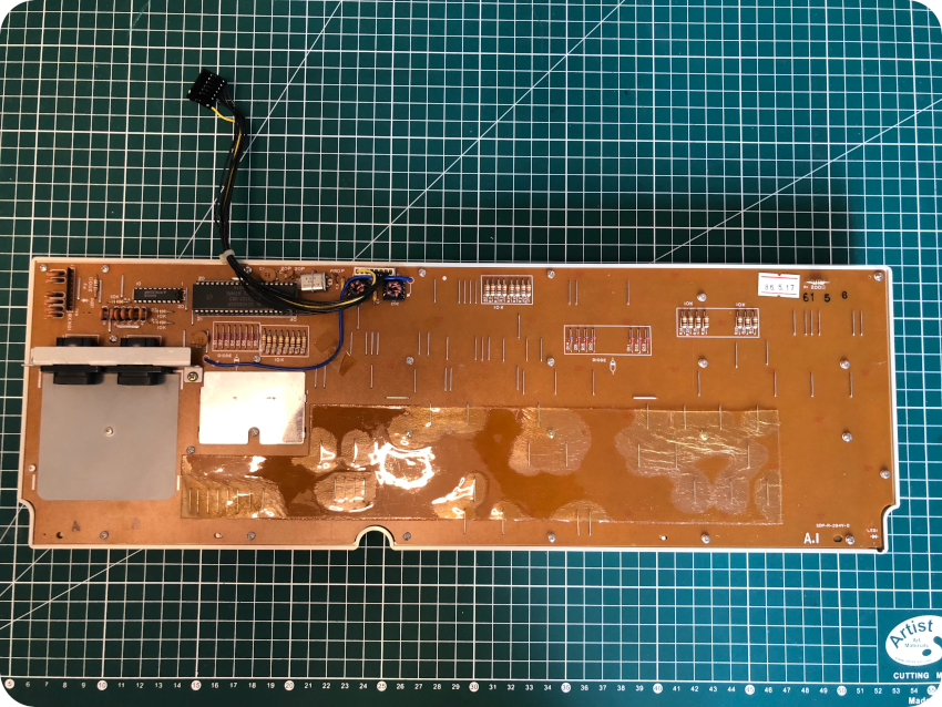
Analysing the mod
Now that all the components are freed from the enclosure, let’s find out what the mod is. My first guess was that it is an A/B switch mod. Was I correct ? Let’s have a look inside:
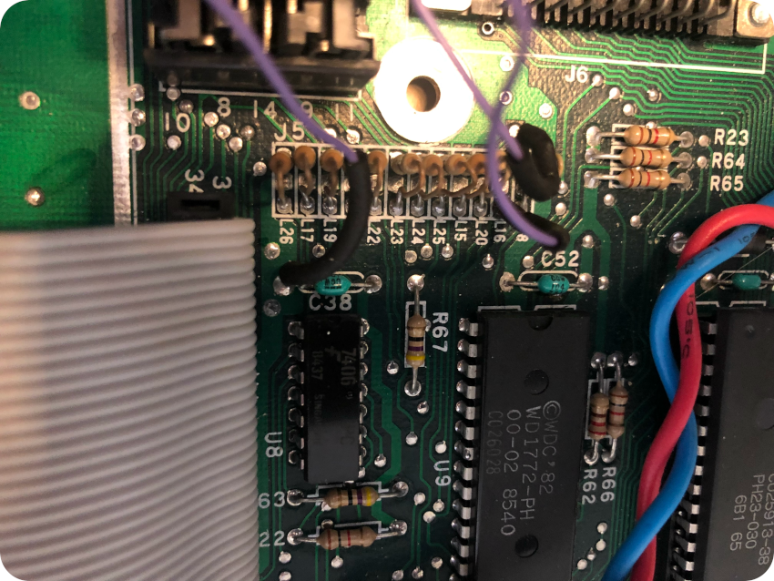
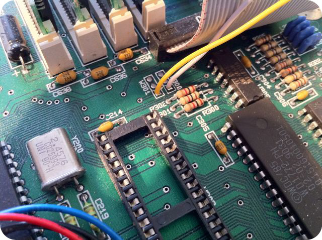
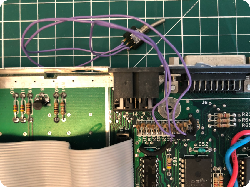
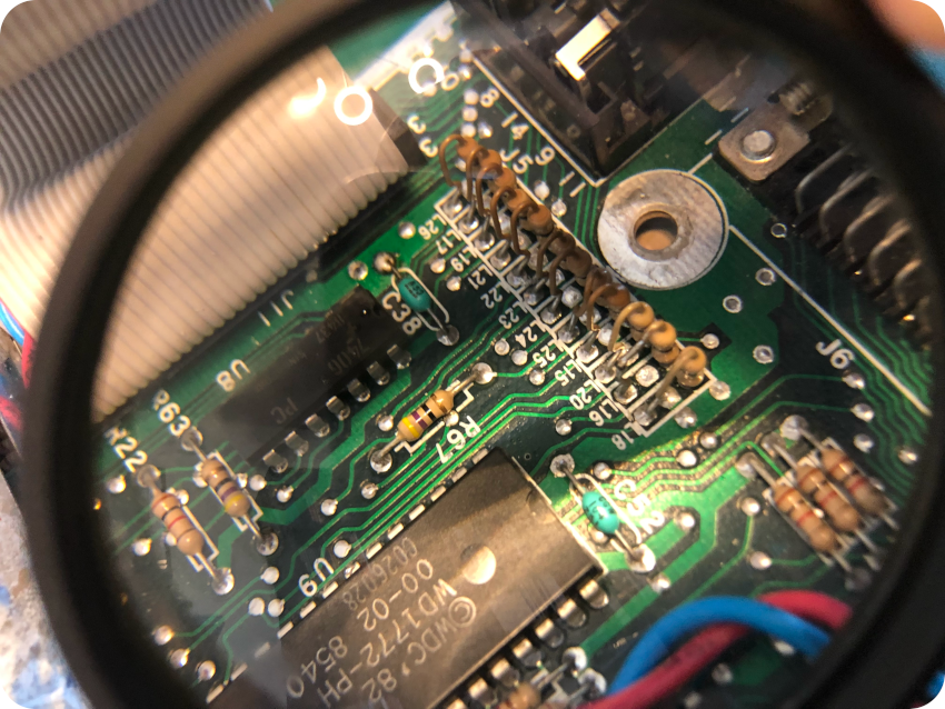
The modification seems to be neatly done (like the cut on the case), and quite simple:
- A 3-wires, 2-position switch
- One of the wire is soldered to capacitor C38
- L16 is cut off, one part of leg being disconnected from the board
- One of the wires is connected to the free leg, the remaining wire being soldered to the board, where the leg was cut off
This … doesn’t look at all like an A/B switch mod ! Indeed, this kind of mod involves
- A DPDT (Double Pole, Double Throw) switch, with 6 wires (image from https://temlib.org/AtariForumWiki)
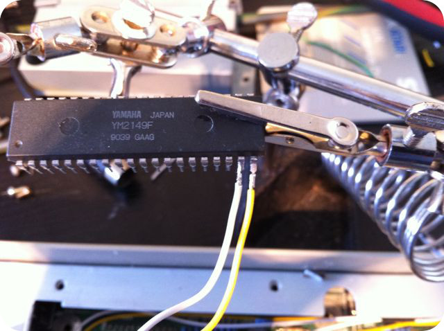
- Removing the Yamaha YM2149F sound chip – also used for the Drive Select (DS) signal – from its socket, bending two legs, soldering 2 wires to them and putting back the chip into its socket (image from https://temlib.org/AtariForumWiki)
- Soldering 2 wires to DS0 and DS1signals (image from https://temlib.org/AtariForumWiki)
This is obviously not the case here ! I was wrong, this it not an A/B switch mod. Back to square one. What the hell is this mod !?
I don’t have any logic probe or any oscilloscope. It then is difficult for me to track and understand signals. Thus, I cruised ST forums and web sites dedicated to Atari ST mods, looking for one that would match … and found nothing similar to this mod. In the end, I had a look at the “La bible Atari” web site. There, I found a link to an interesting article from the Atari 1ST French magazine (#6, March 1988, article by Ange Lartiche):
This two pages article was entitled “Des commutateurs pour mes lecteurs” (“Switches for my drives”):
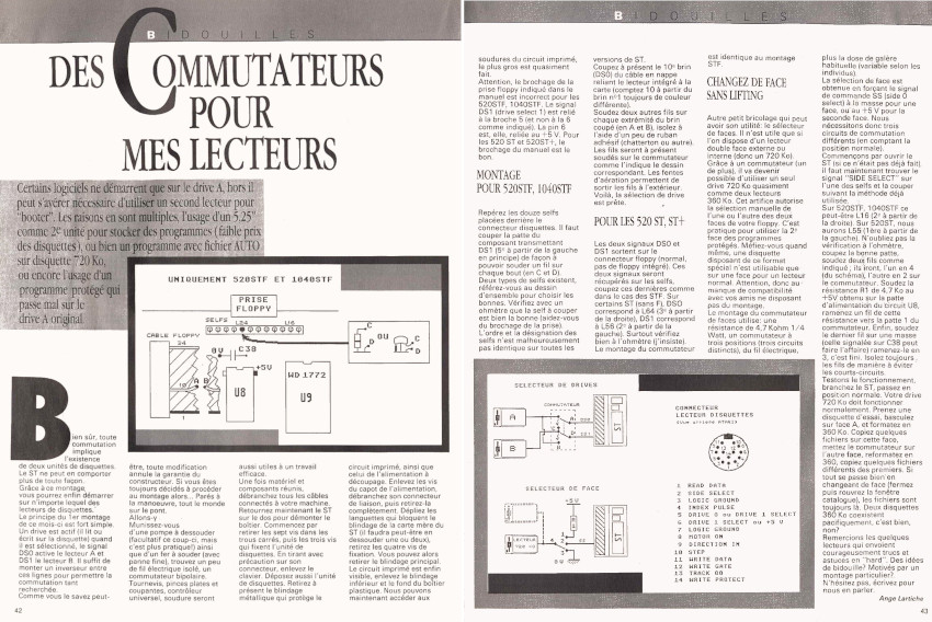
It describes two different mods:
- A drive select mod (A/B switch, but different from the usual Yamaha mod)
- A side select mod
Let’s have a look at the schematics of this second mod. This looks familiar ! Could a previous owner of this Atari have been a reader of “Atari 1ST” magazine ?
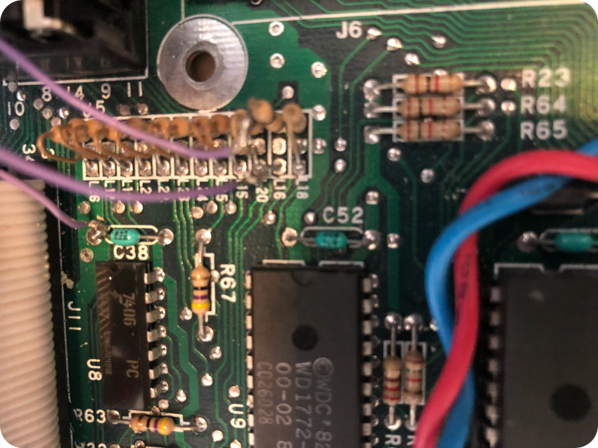
This peculiar mod consists of:
- Cutting L16 (Side Select signal) and soldering 2 wires to the switch. Yes, on the schematics, it points to L24, but only L16 is actually mentioned in the text (page 43)
- Adding a 4.7 kΩ resistor (should be at U8)
- Wiring the last wire to ground on C38
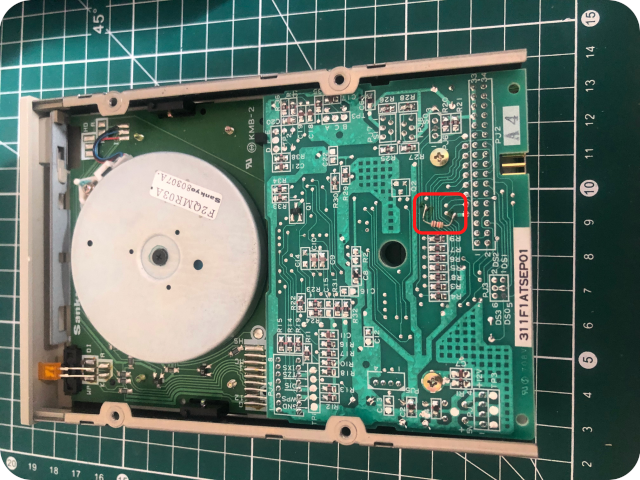
We are getting close. Only … the 4.7 kΩ resistor seems to be missing. But … looking at the PCB of the floppy disk drive, an added 4.7 kΩ resistor can be found. Unfortunately, I don’t have schematics for this drive (a Chinon FB-354 Rev A, as we will see later on). Once again, it is difficult to draw definitive conclusions.
Could this mod is be a “side selection” mod ? As described in this article:
- In middle position, the drive should acts as a usual 2-sided floppy drive
- In left position, the drive should acts as a 360kB floppy drive (selecting side 1)
- In right position, the drive should acts as a 360kB floppy drive (selecting side 2)
With this very peculiar mod, one could use regular 2-sided 720kB-formatted floppy diskettes (middle position), regular 1-sided 360kB-formatted floppy diskettes (middle position) or an highly unusual 2 sided 2×360 Kb floppy diskettes (each side being 360kB-formatted). The switch (left or right positions) allows in this case to choose which side of the diskette to use. I haven’t found any other article mentioning this mod or this kind of usage. In practice, I am not even sure this is a particular useful mod.
Let’s have a look at the mod we have here. It is close, but the switch used here is a 2-position and not the required 3-position switch. Is this mod making any sense then ? Whatever this mod objective was, one thing for sure is that it acts on the Side Select signal (L16). Let’s close this investigation and let’s reverse this damned mod !
Reversing the mod
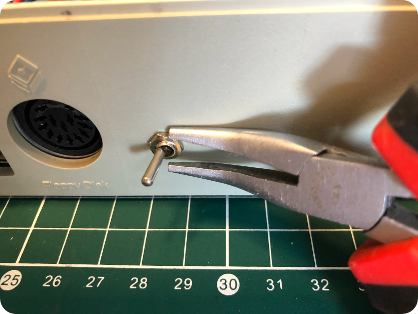
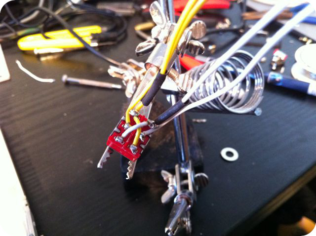
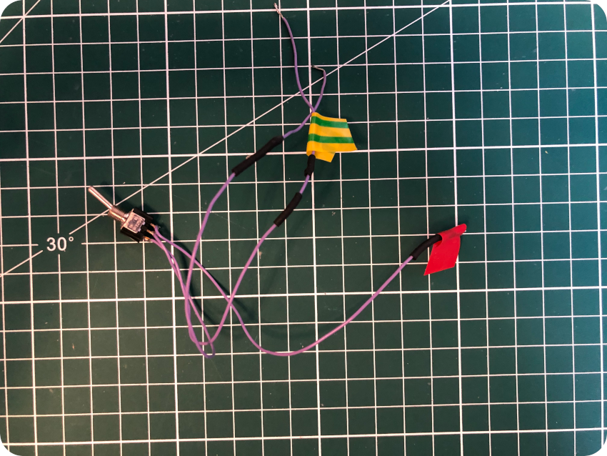
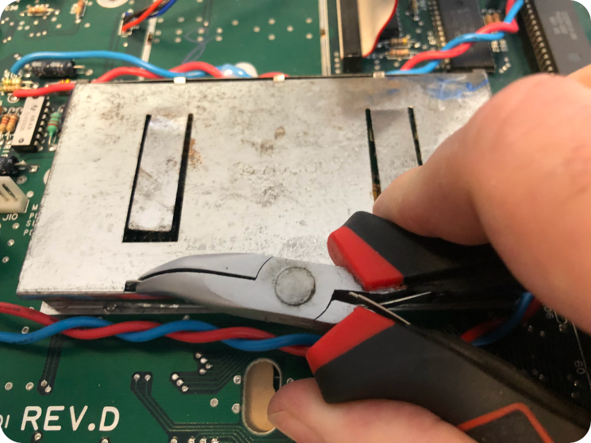
First thing to do, in order to reverse the modifications, was to remove the heat shrink tubing, to get access to the solder:
Once removed, I fired up my soldering iron, to remove the 3 wires and the switch from the board:
Then I flew fresh solder into C38, soldered back L16 and checked for continuity with a multi-meter:
Once done, I tested the Atari ST with the demo diskette: the Atari booted right away and launch this damned soccer game. The mod is gone for good !
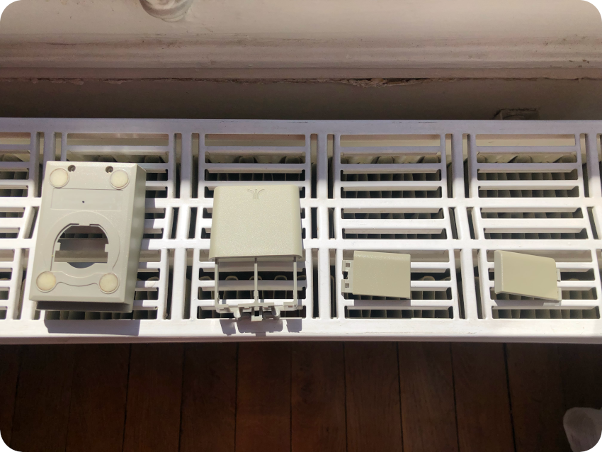
It was time for the last step: covering the hole in the back of the enclosure, where the switch was screwed. I figured out the cap from the back of a Bic Cristal pen would exactly fit the hole. I sprayed on it the same light grey paint I used for the mouse button of the Mac Plus:
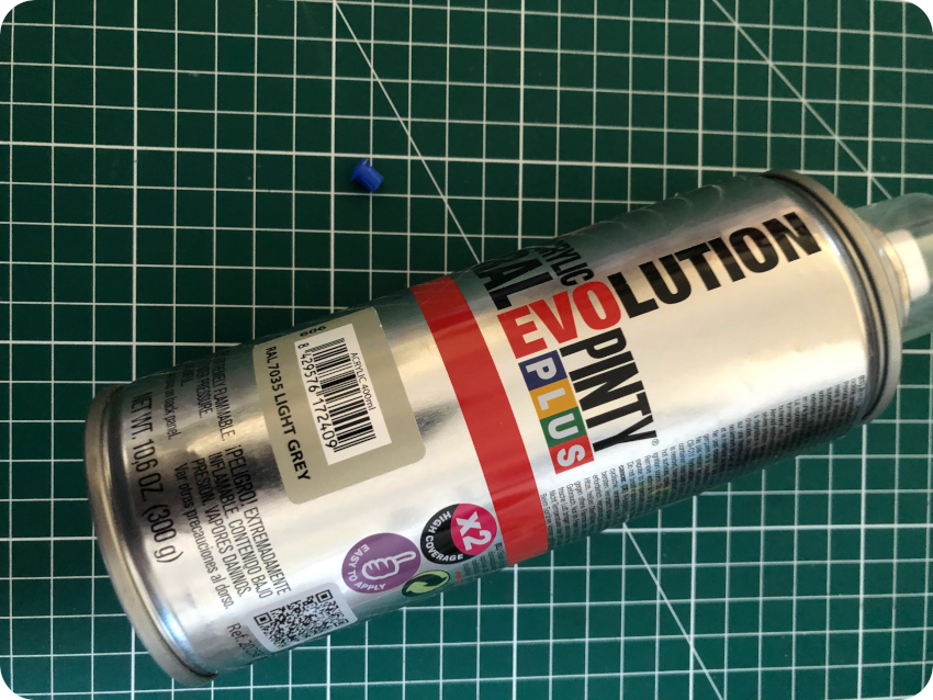
And … voilà ! The color is no perfect, but it is close. The cap fits well and closes this damn hole:
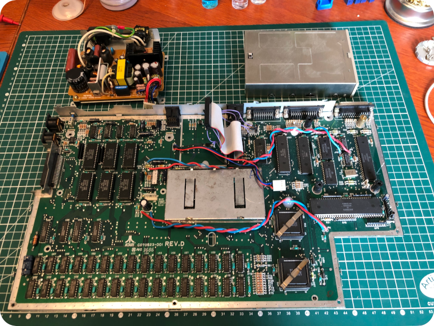
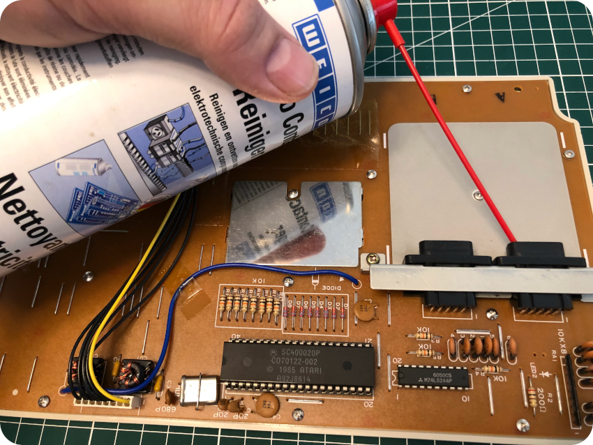
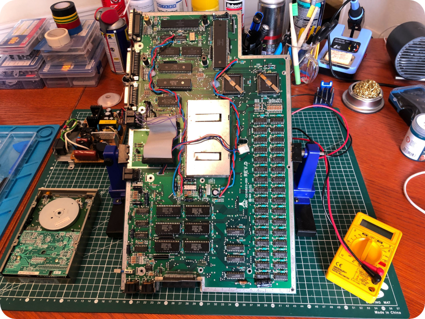
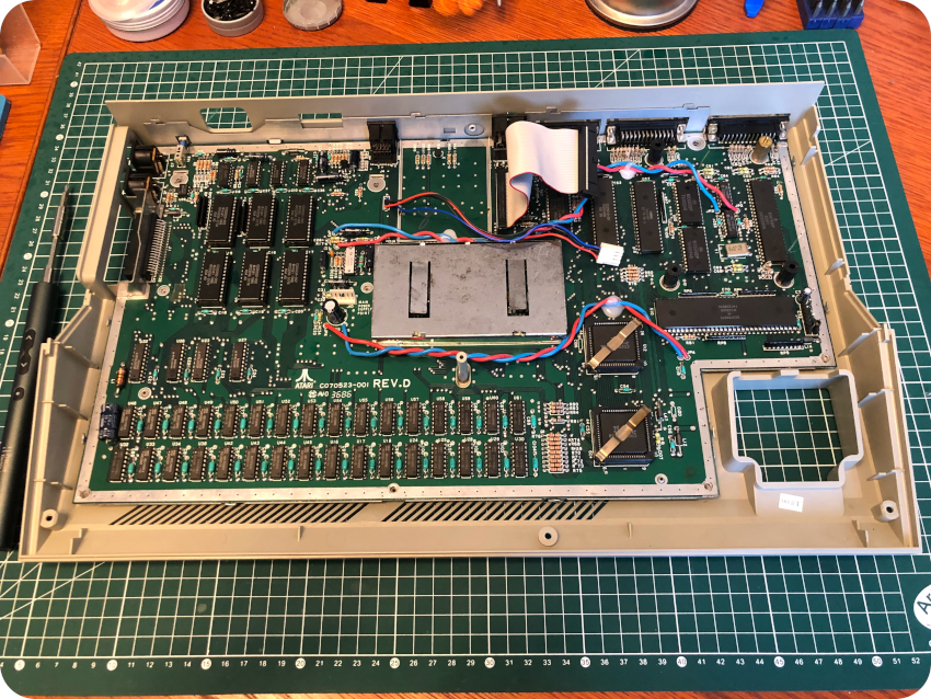
The main PCB
Now that the mod is reversed, let’s take care of the motherboard:
This board was really clean. Just a bit of dust, easily removed with compressed air. I took the time to re-seat all socketed components:
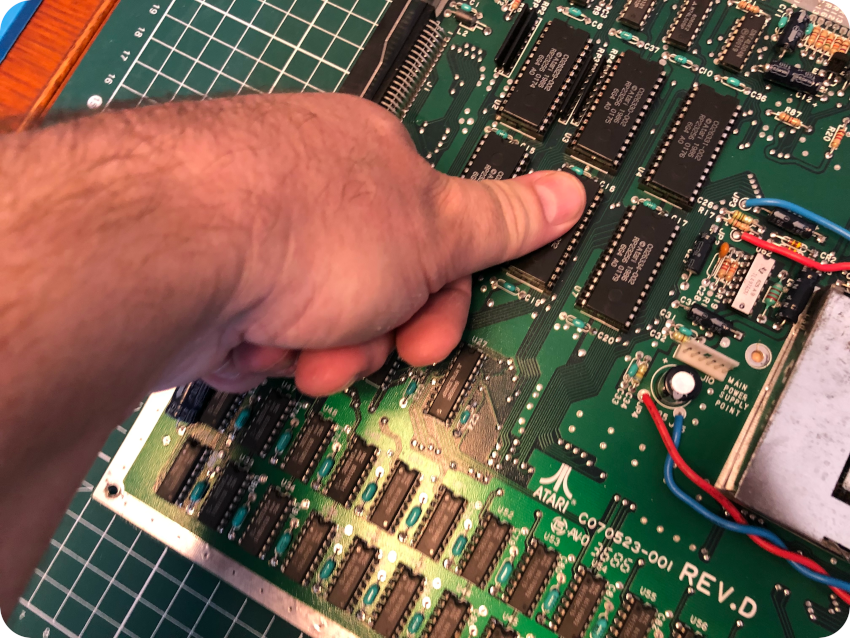
I inspected all solder joints and electrolytic caps. Everything looked nice and in good conditions (I may recap nevertheless the PSU). Then I cleaned both sides of the board with IPA, a toothbrush and a micro-fiber cloth:
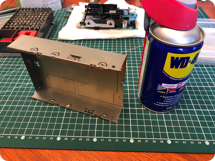
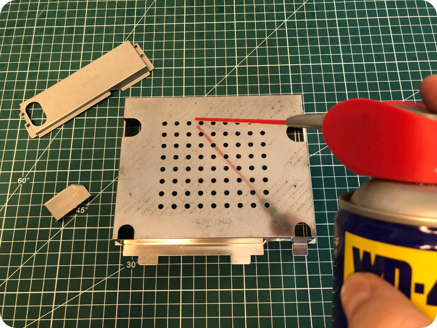
I opened up the shield protecting the video components (the SHIFTER):
I used WD-40 to clean the metal shield:
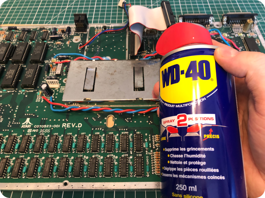
Finally, I sprayed contact cleaner on all connectors (internal and external):
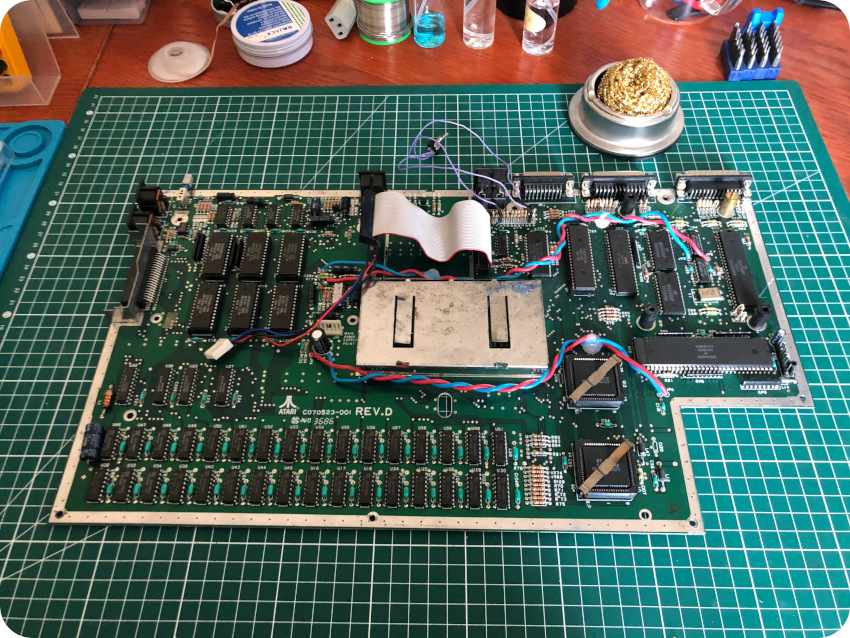
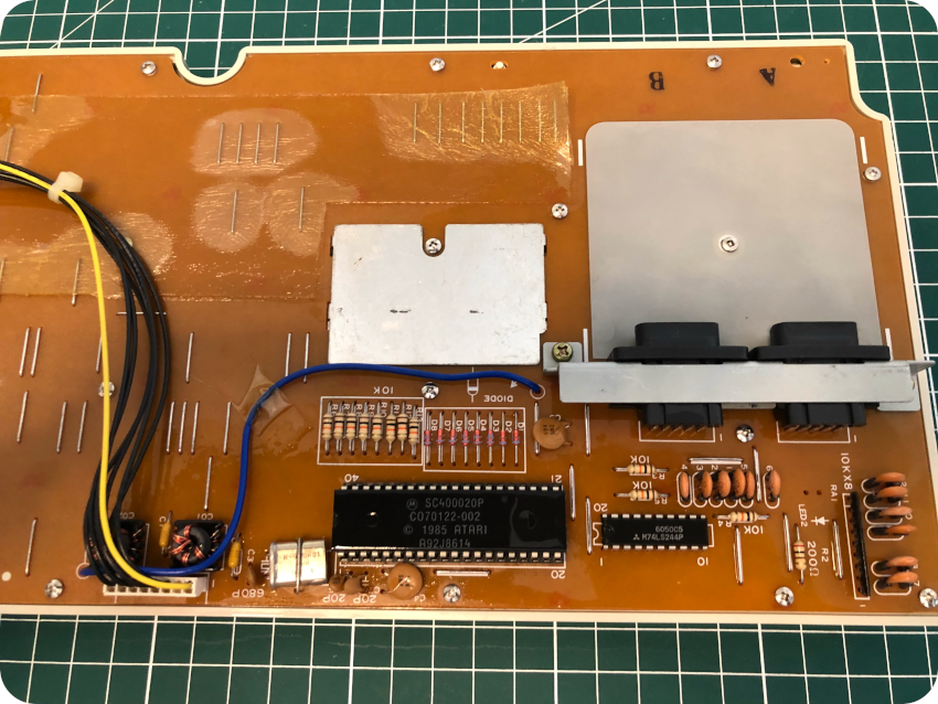
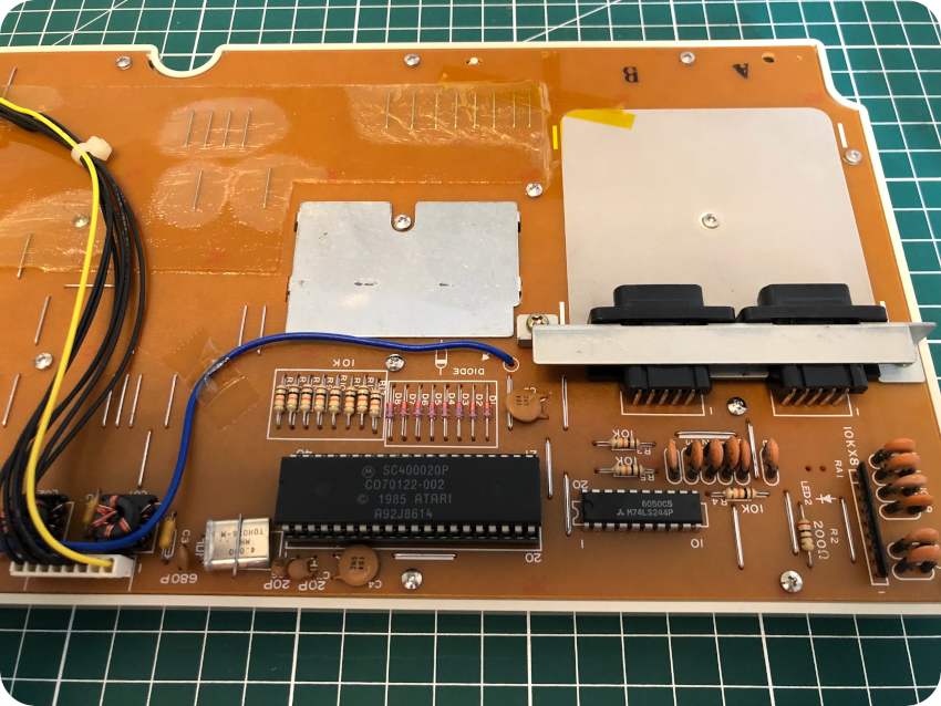
This motherboard was inspected and cleaned up. Now, let’s take a detailed look at it !
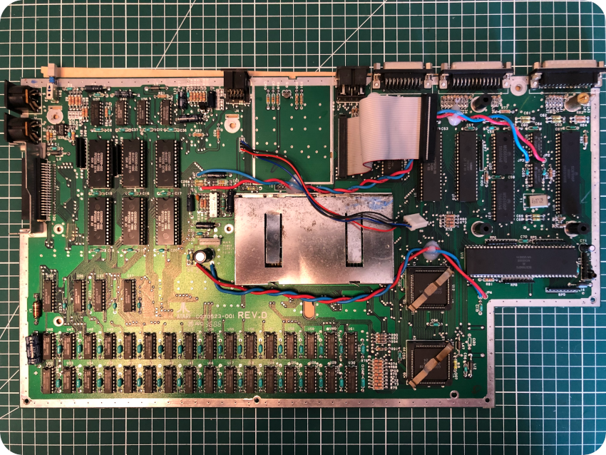
This is a C070523-001 REV. D board, from 1986:
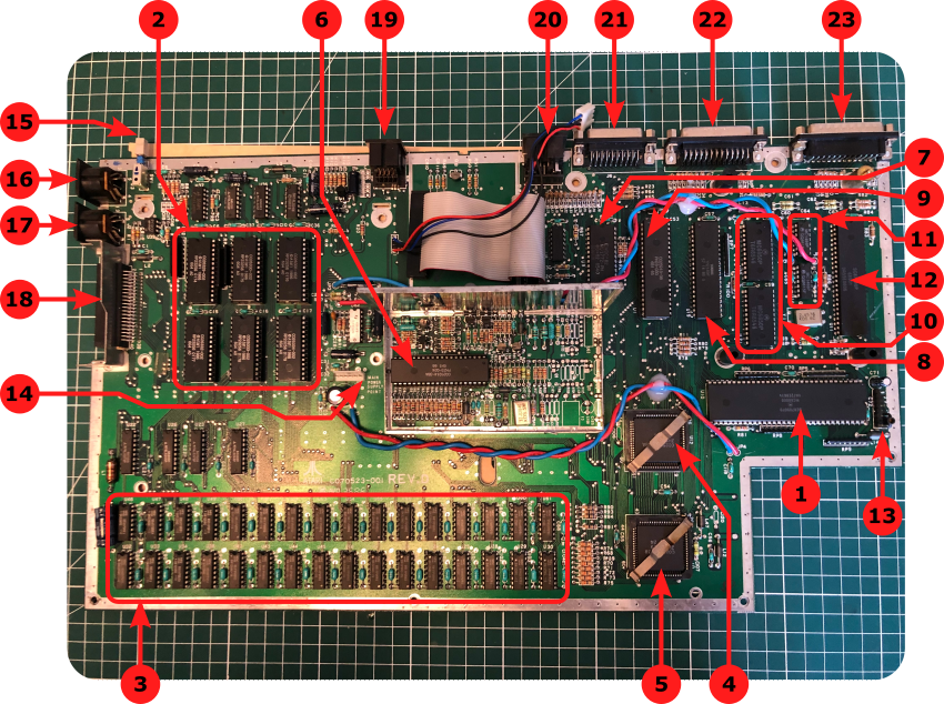
Here are the main components of the motherboard:
- Microprocessor: the Atari 1040STF is powered by a Motorola 68000 16-/32-bit CPU, clocked at 8 MHz. This processor has a 32-bit instructions set, with 32-bit registers, a 16-bit internal data bus (hence the name “ST” for “Sixteen / Thirty-two”) and 24 address bits (16-megabyte address range)
- ROM: this board is an early model, with 6 TOS 1.0 ROM chips, labelled “C026329-002”, “C026330-002”, “C026331-002” (LO) and “C026332-002”, “C026333-002”, “C026334-002” (HI). Later models would have only 2 ROM chips instead of 6.
- RAM: the 1040STF is equipped with 32 DRAM chips, directly soldered to the motherboard. The 1040ST was the first computer to break the $1000/megabyte price barrier.
- GLUE: the Atari ST has 4 specially developed ICs (GLUE, MMU, DMA and SHIFTER). They play a major role in the low price of the ST, reducing the number of TTLs (reduced to 8 chips on this board). These IC’s are designed to work in concert with one another. Form example, the DMA chip cannot operate alone. The GLUE holds the entire system (hence its name), including decoding the address range and working the peripheral ICs.
- MMU: the MMU (Memory Management Unit) ensures the management of RAM. It also works with the SHIFTER to produce the video signal. It is also manages the discs transfers done by the DMA circuit.
- SHIFTER: the SHIFTER converts the information in video RAM into impulses readable on a monitor.
- Floppy Disk Controller: a Western Digital WD-1772 40-pin DIP floppy controller.
- Programmable Sound Generator: the Yamaha YM2149 provides three-voice sound synthesis. It is also used for floppy signalling, serial control output and printer parallel port.
- DMA: The DMA (Direct Memory Access) oversees the floppy disk controller and an external hard disk. The DMA is joined to the processor’s data bus to help transfer data.
- ACIAs: the ACIAs are Asynchronous Common Interface Adapters. The Motorola MC6850 chips enable the ST to directly communicate with MIDI devices and keyboard (two chips are used, 31.250 kbit/s for MIDI, 7812.5 bit/s for keyboard).
- Serial Controller: the RS-232 serial communication are handled by a Motorola MC1489 chip.
- MFP: the Mutli-Function Peripheral (MFP) chip handles the 8-bit parallel port, 4 timers, 16 possible interrupt sources, built-in serial interface.
- Keyboard: internal connector for the keyboard.
- Power Supply Unit: internal connector for the PSU.
- Reset button: allows a warm restart of the ST (meaning that is restart the ST via the Reset Vector, but doesn’t entirely wipes out all memory)
- MIDI: MIDI Out DIN-5 connector.
- MIDI: MIDI In DIN-5 connector.
- Cartridge: the cartridge slot can be used for inserting ROM cartridges (128KB max)
- Video: RGB video out DIN-13 connector.
- Floppy Disk Drive: DIN-14 connector for external Floppy Disk Drive.
- DMA Interface / Hard Disk Drive: Up to 8 external devices – such as hard disks, networks or the Atari Laser Printer) can be connected to this 19-pin D-SUB female connector. Hard disks are using the ACSI (Atari Computer System Interface) interface.
- Parallel Port: a standard Centronics (25-pin D-SUB female) parallel printer can be connected to the ST via this interface.
- Serial Port: a RS-232 interface (25-pin male D-SUB) for serial communication.
Note:
- Information on hardware was sourced from Wikipedia, from “Anatomy Of the Atari ST” (by K. Gerits, L. Englisch and R. Bruckmann) and from https://info-coach.fr/atari/hardware/.
- Mouse & Joystick connectors (DB9 connectors) are located under the keyboard
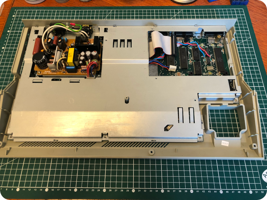
The internal Power Supply Unit
Let’s now focus on the internal PSU. There exist several PSU models for Atari STs: MITSUMI SR98, DVE DSP-508A, ASP34-2, etc. This one is a Tokin 4501E1:
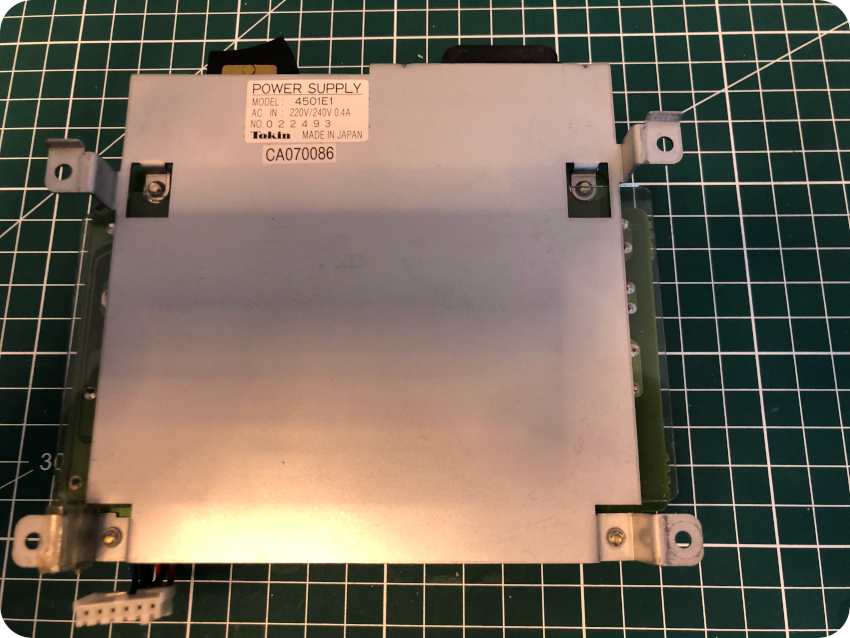
Let’s open it:
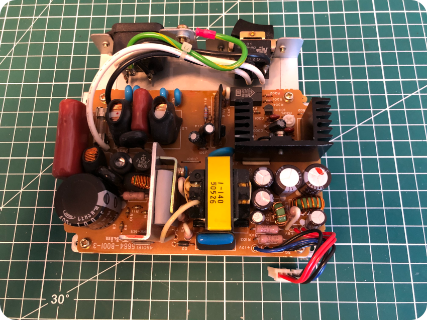
Just like the motherboard, the PSU is very clean, which is nice for a change. I proceed with my usual cleaning workflow: compressed air, IPA & soft toothbrush, micro-fiber cloth and contact cleaner.
I did my usual inspection routine (looking for bad solder joints and bulged electrolytic caps). All looked very nice.
While testing the Atari ST with the demo diskette, I noticed a bit of noise in audio, as well as video dimming as the motor of the disk drive powers up and a bit of flickering while accessing the disk. Maybe a recapping is needed. Nevertheless, from what I read, this may be typical of this particular PSU, which is not the best one (reasonably good power regulation, but poor peak power capability), and recapping would not help. For now, I will let things as they are.
Nevertheless, during most of the tests I did, I took care to left open the top cover of the Atari ST, as the weather was getting really hot here in France during summertime (around 40°C).
Servicing the floppy disk drive
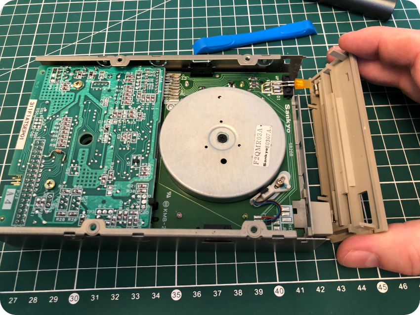
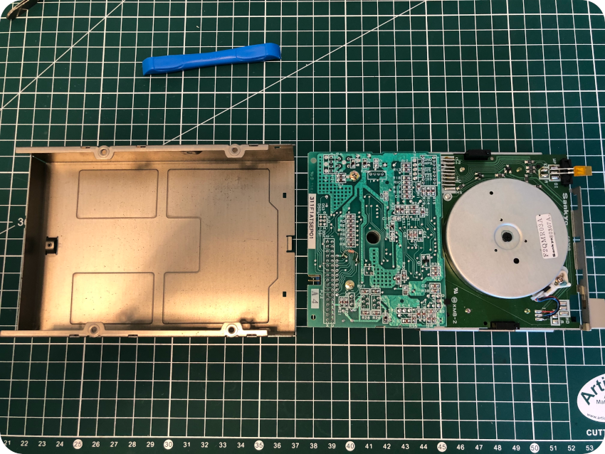
Let’s have a look at the floppy disk drive that had been replaced by a previous owner:
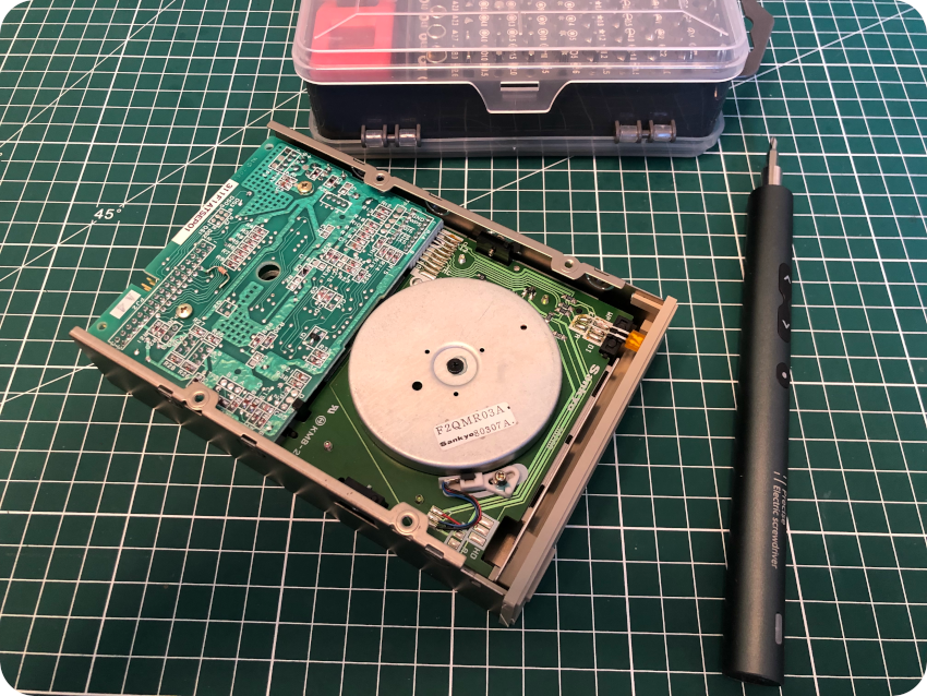
Well … this is a Chinon FB-354 (Rev. A):
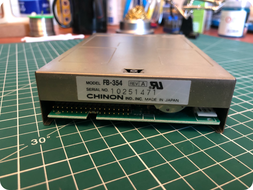
This is a bit of a surprise. Atari had different floppy drive suppliers: Sony, Epson and, indeed, Chinon. It means that this replacement drive is era appropriate, which is very nice.
But, with this kind of bezel … this drive may have been “borrowed” from an Amiga. Yes, Atari ST’s old nemesis used Chinon FB-354 drives. This would be wild and highly heretic, but fun ! Is this why there is an added resistor on its PCB (or was it part of the switch mod, or just added at factory for some reasons) ? My knowledge on that topic is not deep enough, I will have to investigate more …
Anyway, let’s service this drive !
First, let’s unscrew the chassis:
Then, let’s remove the front bezel:
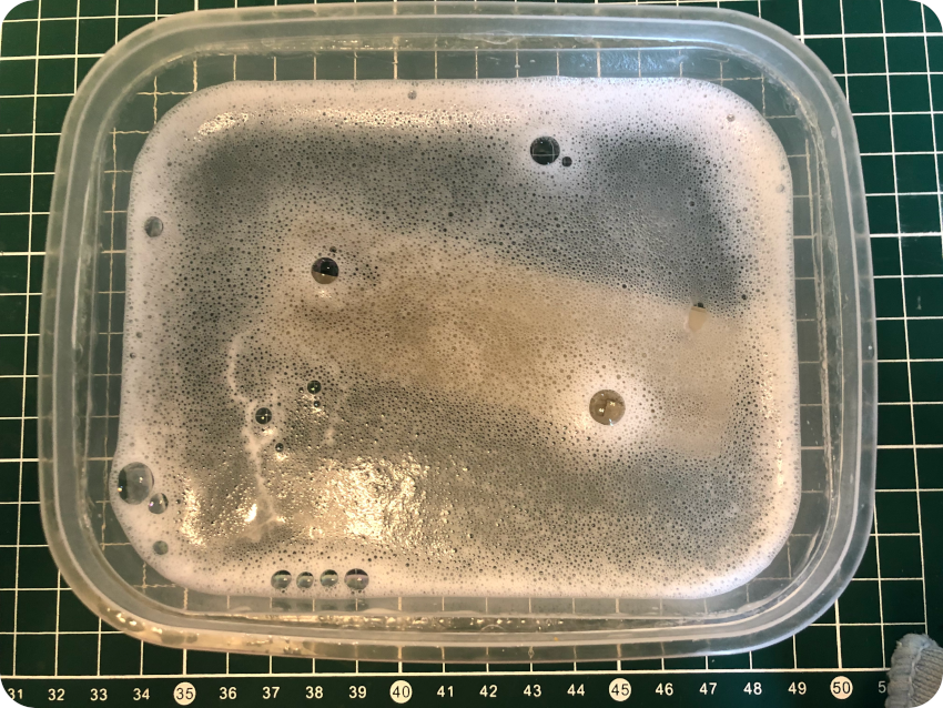
While I let the front bezel soak into warm soapy water …
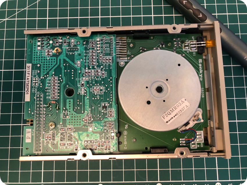
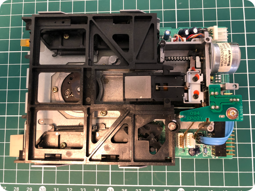
… I took apart the disk drive itself:
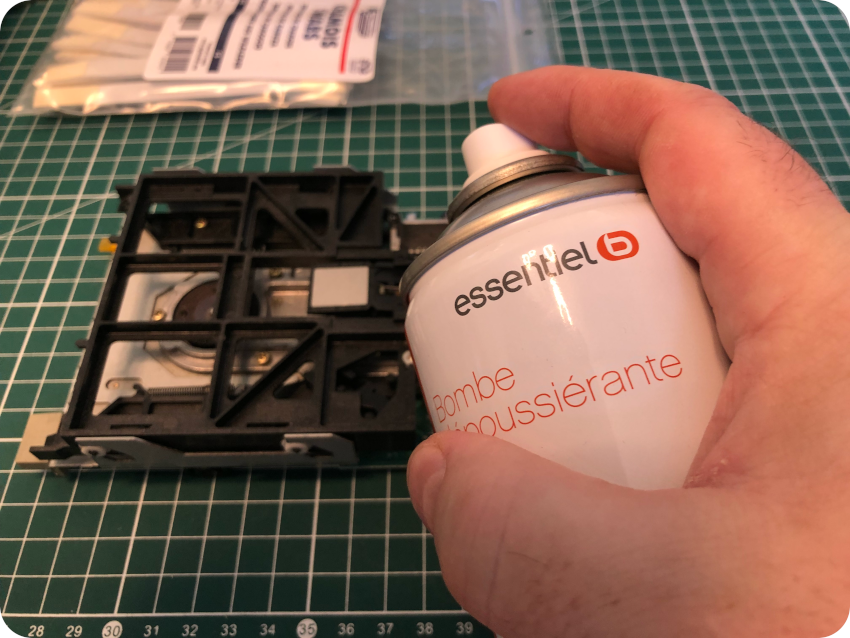
I blew compressed air:
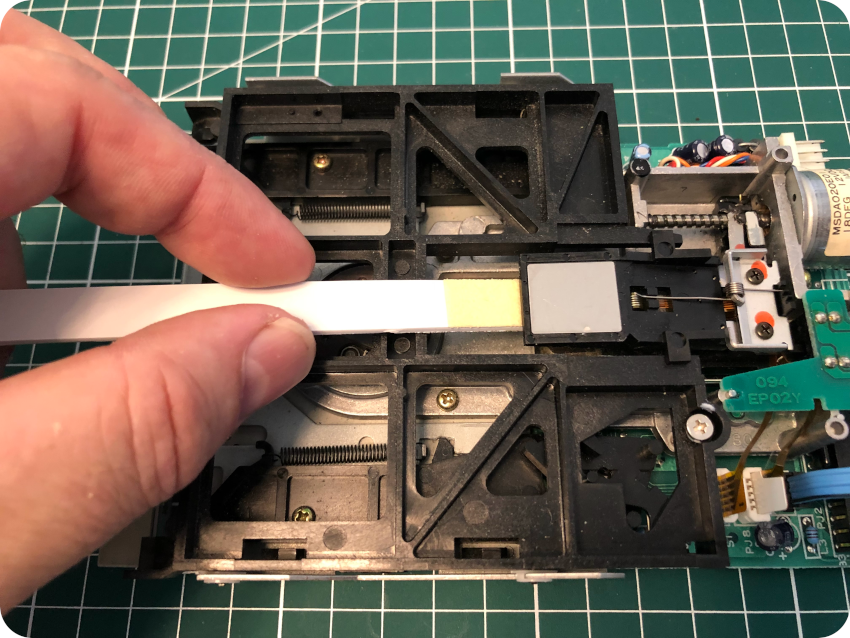
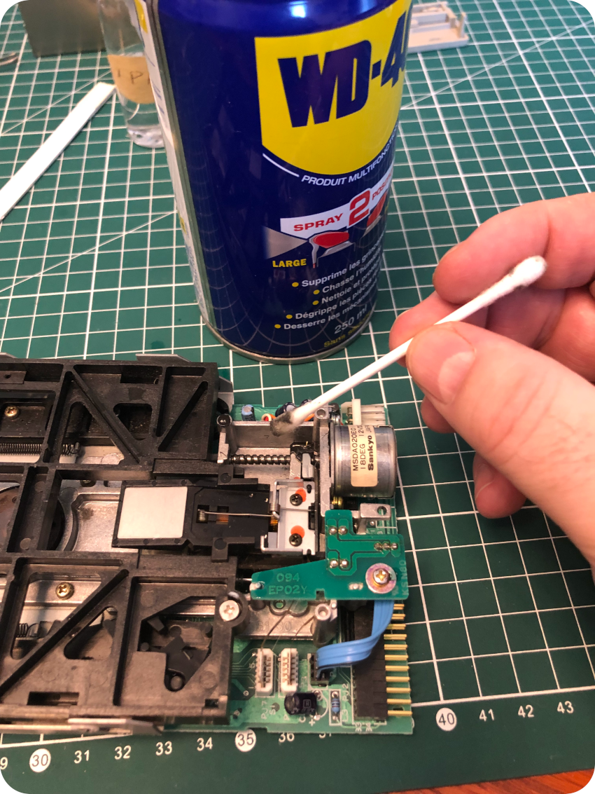
Then cleaned the head with IPA on a chamois swab:
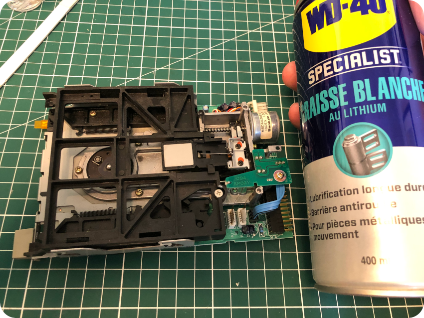
I cleaned the mechanical parts with WD-40:
Then I applied white lithium grease on them:
I cleaned the PCB with IPA:
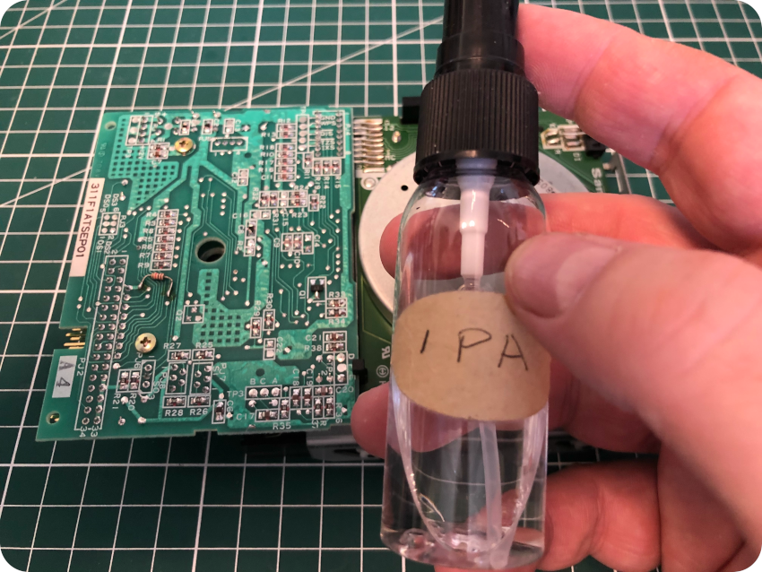
Then I took care of the connectors with contact cleaner:
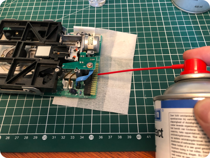
Finally, I cleaned up the chassis with WD-40:
Then, it was just a matter of putting things back into place. There we go, a serviced floppy disk drive !
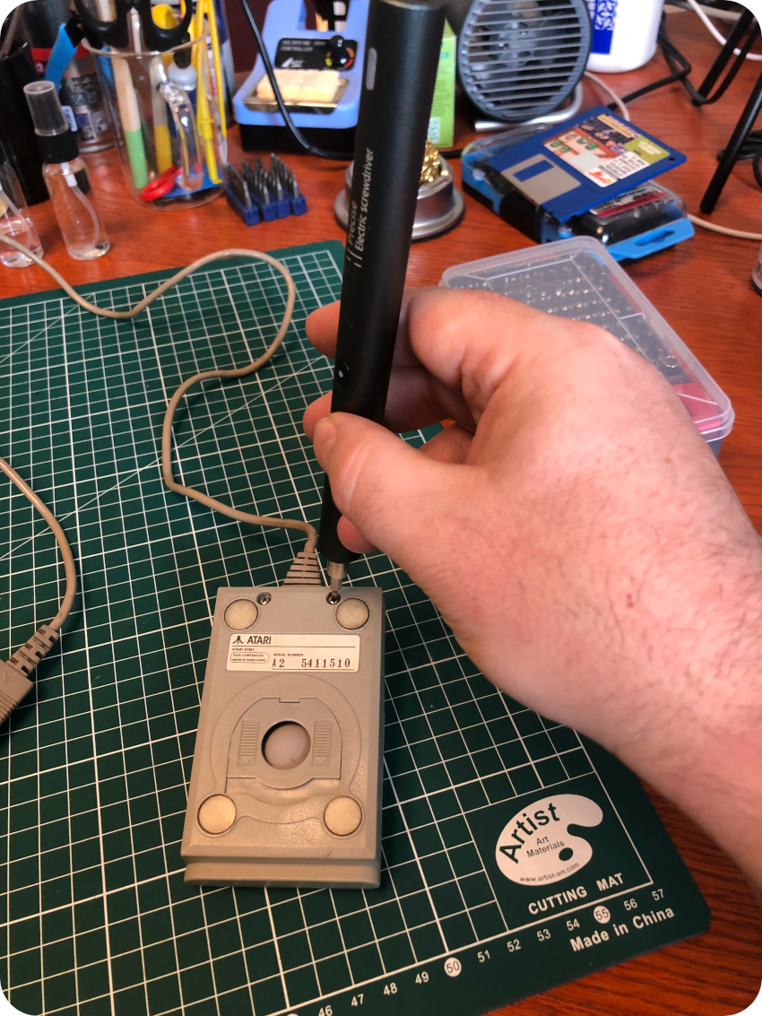
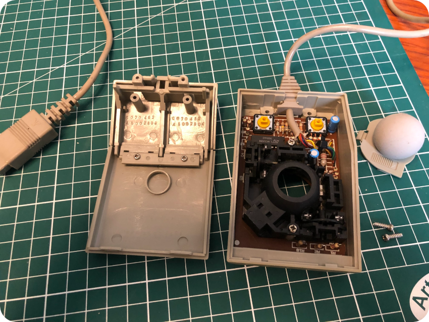
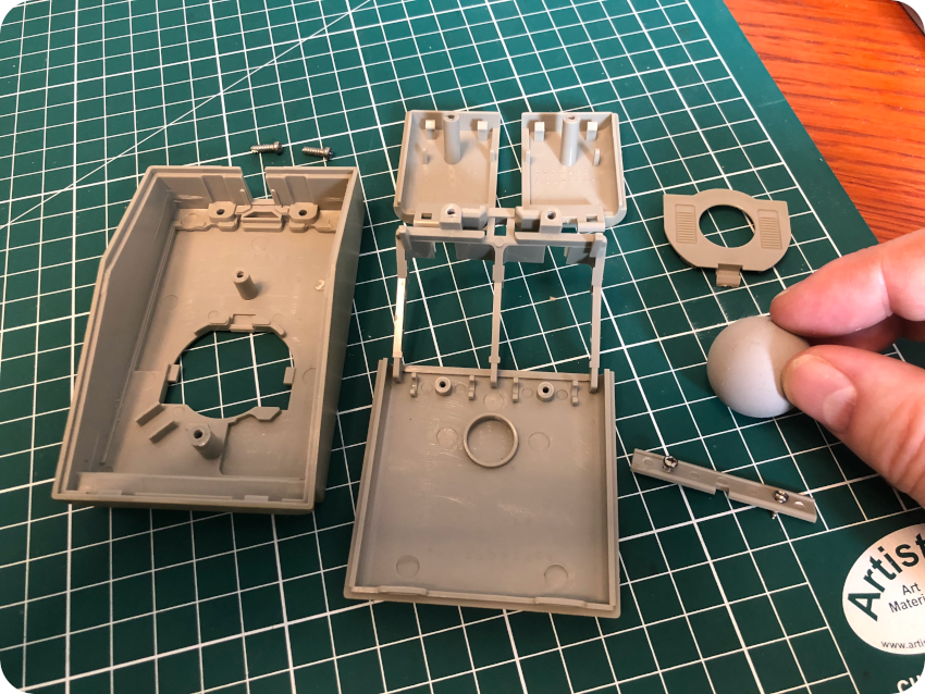
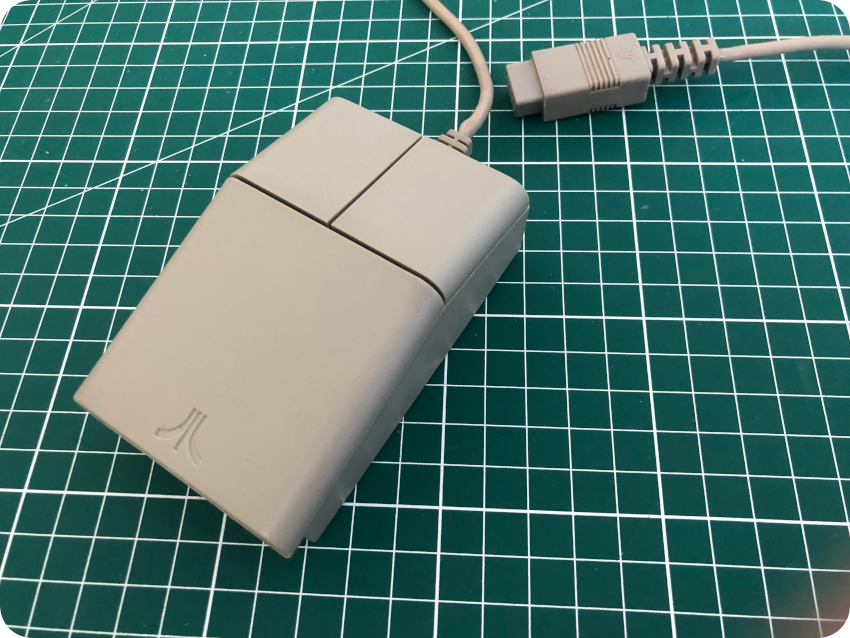
Servicing the mouse
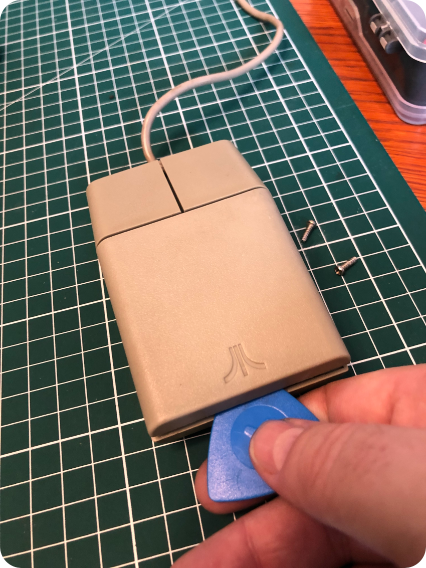
Let’s take care of the mouse ! It is rather easy to open, with just two screws:
I then removed the ball from its housing:
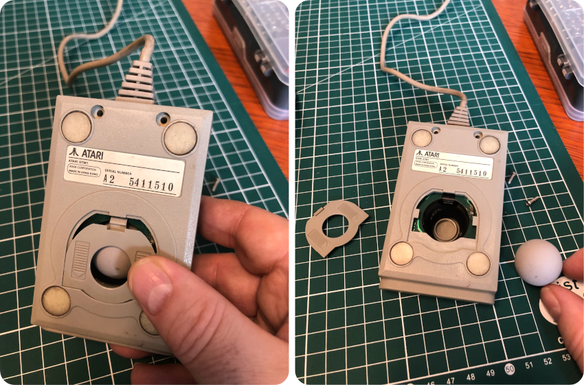
And I opened up the mouse with a plastic prying tool:
Only two screws are holding the mouse’s PCB:
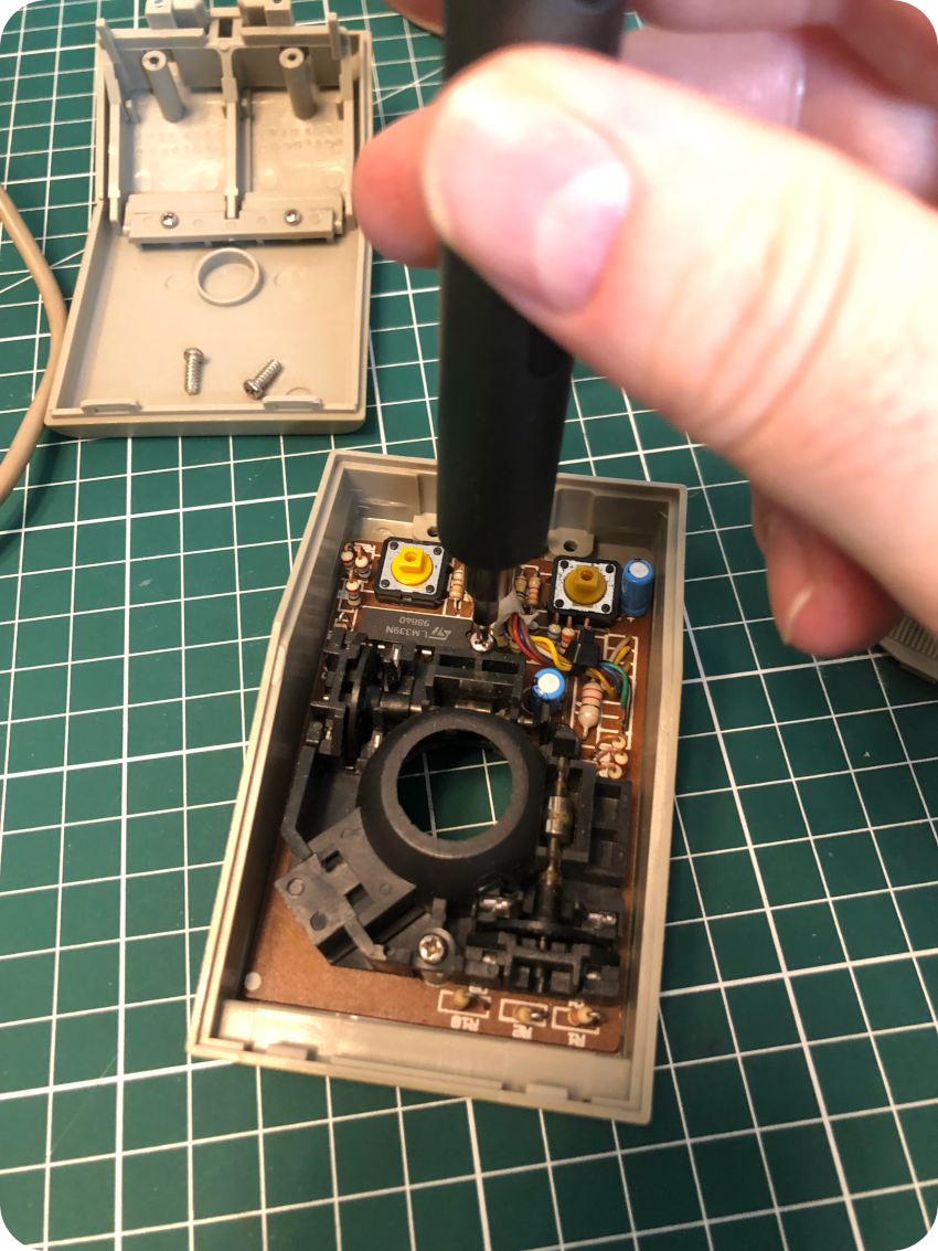
Two screws are used to hold the buttons:
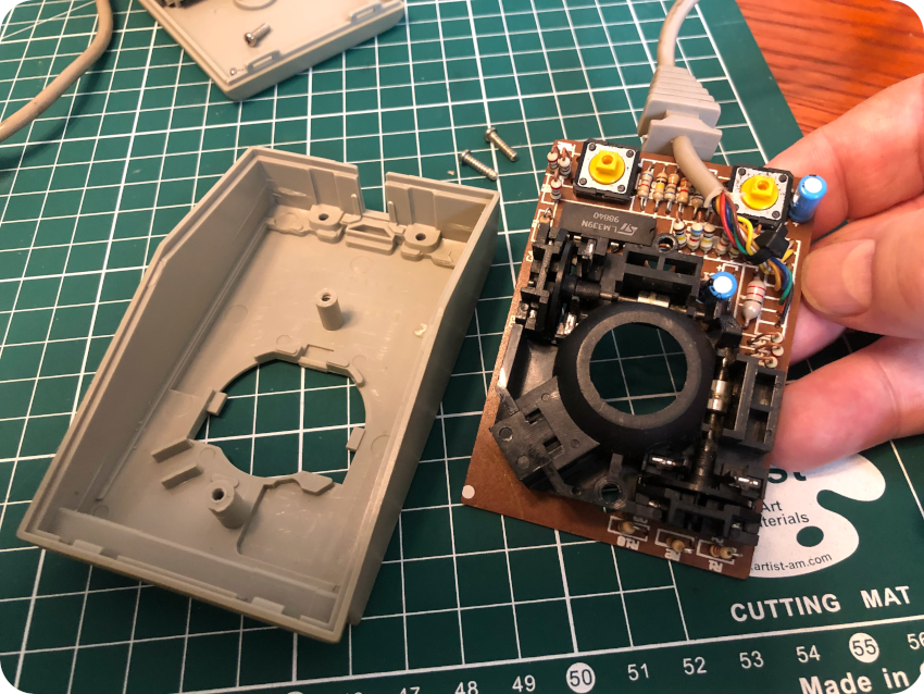
The mouse is now completely taken apart:
It was time for the mouse to take a warm soapy bath:
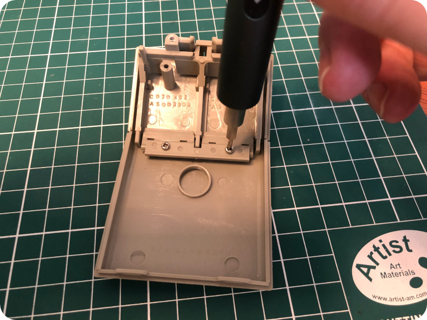
I finished the cleaning process with a toothbrush:
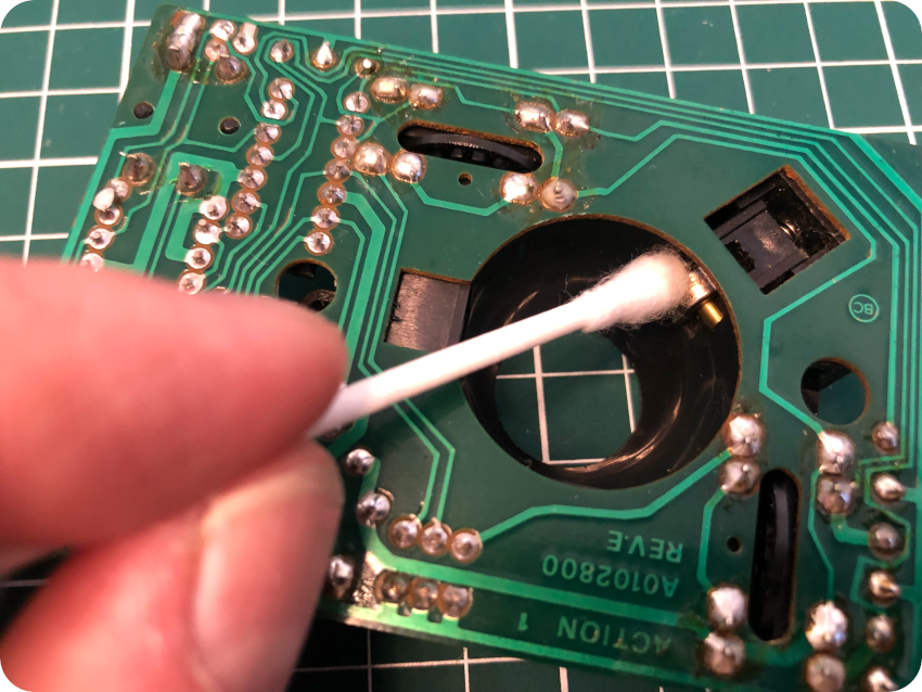
Then, I took care of the PCB with IPA, and I cleaned the mechanical parts of the mouse:
Sunbrighting the mouse
The mouse, as advertised, was a little yellowed. I decided, from previous experience, not to retrobright the mouse. Instead, I decided to simply sunbright it. I let the mouse under direct sunlight a few hours a day, for about two weeks:
My lovely dog also took sunbathes (and naps) during that time. Yes, Shiba Inus love sunbathing (according to an old Japanese saying, Shibas are a quarter dog, a quarter cat, a quarter human and a quarter monkey. The cat part plays an important role here):
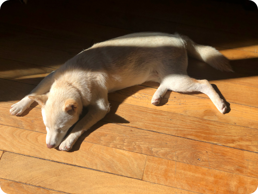
The results were pretty good. The yellowing disappeared. The mouse has now the same color as the ST enclosure:
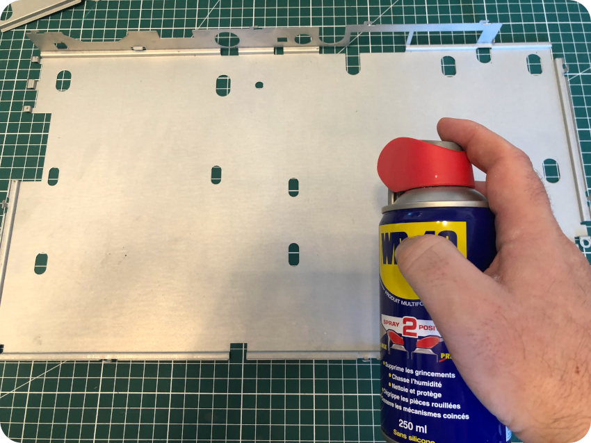
Putting things back together
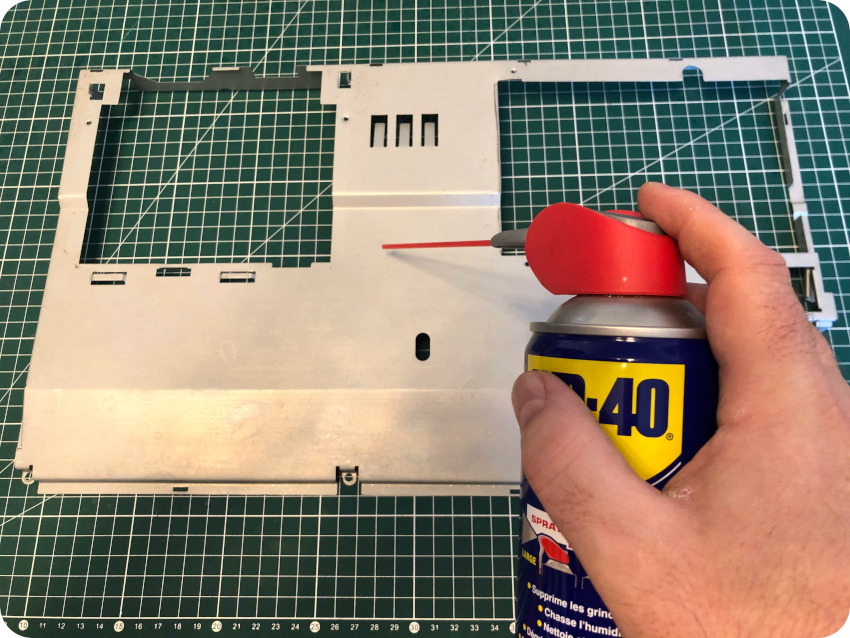
Let’s put things back together. There is a lot of shielding ! I took care of them with WD-40:
Then, is was just a matter of putting things back in the right order, starting with the bottom shield:
Then its cardboard insulator:
Then the motherboard:
Then the PSU and the top shield:
Then the PSU shield and the floppy disk drive:
Then the keyboard:
As a finishing touch, I took care of the old sticker on the bottom of the enclosure, with the wrong “1040STFM” mention:
I fired up Inkscape and redrew a sticker, with the proper mention “1040STF”:

There goes the result, not perfect, but close enough:
I flipped the case and glued the new sticker to the enclosure:
There we go !
Now that the hardware is done, it is time to tackle the software !
Software for Atari ST
My goal was to reproduce a set of diskettes for apps, games and various versions of the ST System (TOS) on them. This is why I bought a set of old Double Density 3″1/2 diskettes (unknown conditions), an external USB 3″1/2 floppy disk drive and New Old Stock stickers to label them properly.
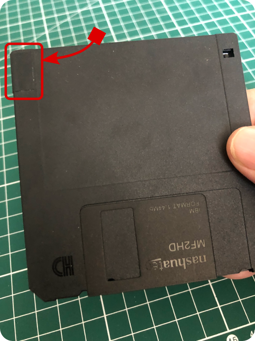
I knew some of the DD 3″1/2 diskettes could fail, this is why I also bought sets of New Old Stock High Density 3″1/2 diskettes. Without modification, Atari 1040STF can only use DD 3″1/2 diskettes (720kB). HD 3″1/2 diskettes (1.44Mb) can nevertheless be formatted as DD. It is commonly said that HD diskettes used as DD diskettes are less reliable. At least form me, it turned out to be very reliable.
Externally, DD and HD 3″1/2 diskettes only differ by a hole on the side. This hole has to be covered with masking tape for some floppy drive to recognize them as DD diskettes:
It turned out that:
- for the (replaced) internal ST floppy drive: HD diskettes can be DD-formatted with or without the masking tape;
- for my external USB floppy drive: DD-formatted HD diskettes can only be used when the hole is tapped. I thus tapped all the New Old Stock HD diskettes.
Creating new diskettes
Creating new diskettes is not straightforward.
First, let’s have a look at diskette images, from which one can create diskettes. These images, containing software, are mainly used by emulators. They are commonly available on dedicated web sites, such as Atari Mania, Planet Emulation and many others.
On these sites, you will usual find images using these formats (see https://info-coach.fr/atari/software/Images-formats.php for more details and other formats):
- ST: This is the most simple format, since it is a straight copy of the readable data of a disk. It does not allow copying copy-protected disks. This is the most common format for ST disk images.
- MSA: This acronym stands for Magic Shadow Archiver. It is supported by almost all emulators. It contains the same data as the ST format, the only difference is that the data is compressed.
- STX: This image format was defined by the PASTI initiative (Atari ST Imaging & Preservation Tools). These tools can virtually create image of any ST disk, including copy-protected ones.
It is not possible to create a protected disk from an STX image. Thus, I focused on ST formatted disk images, the most commonly available ones. It is always possible to convert MSA into ST anyway.
The easiest way for making floppies from disk image files (ST or MSA) is to use the Floppy Imaging & File Transfer (FloImg) from P. Putnik (aka PP):
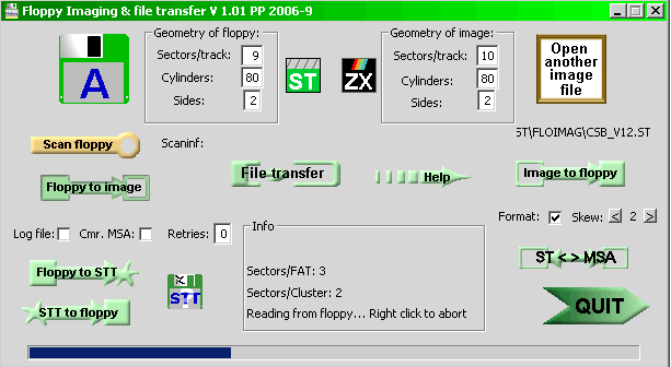
It works on Windows systems … so I had to borrow my wife’s PC. I knew that they were little chance for it to work, since it is designed for built-in floppy drives and not USB external ones. The first thing to do is to install fdrawcmd (from PP) on Windows. And this poor excuse for an operating system refused to do so. Actually, I could not even format a DD diskette on Windows 10. Windows did what it is best at: making me swear and switch back to real operating systems.
I actually have an old internal 3″1/2 PC floppy disk drive, and could have used a KryoFlux floppy controller. KryoFlux is a USB-based device designed for software preservation, in which you can plug a PC floppy disk drive:
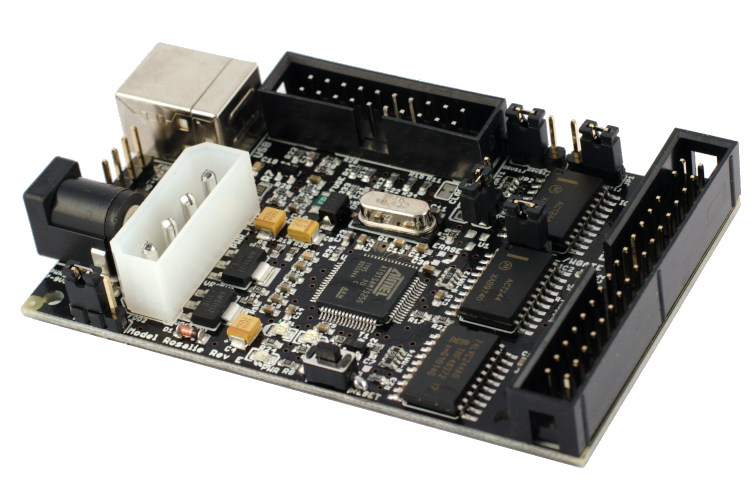
It can save raw stream and support sector formats for Acorn Electron, Amstrad CPC, Archimedes, Atari 8-bit, Atari ST, Apple, Commodore 64, Commodore Amid, MSX, IBM PC, and many others. And it can write back to disk.
But I had enough invested, and I took another path: I simply connected my external USB floppy disk drive to a GNU/Linux system. I had a RecalBox system sitting right next to the Atari ST. It was worth a try:
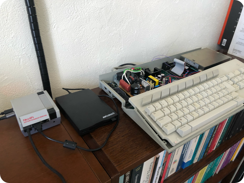
The GNU/Linux system recognized the floppy disk drive as a TEAC device. I formatted a diskette on the Atari ST (720kB, double-sided), then inserted it into the USB floppy disk drive. I could right away mount the diskette as a MS-DOS disk, and could write data … that could also be read back by the Atari ST. Good. I had a way to exchange files between the two systems.
Indeed TOS and MS-DOS formats are very close. Both DOS and TOS use the FAT format. There are nevertheless slight differences on the way the allocation table of the disk is used. TOS versions from 1.04 onward are 100% compatible with MS-DOS. Alas, this 1040 STF runs TOS 1.0.
There are thus a few caveats. I did a few experiments. For example a 1-sided ST formatted disk (360kB) could be read under GNU/Linux. Adding a file from GNU/Linux would work (and could be read back from GNU/Linux), but would result in mangled data when read from the ST
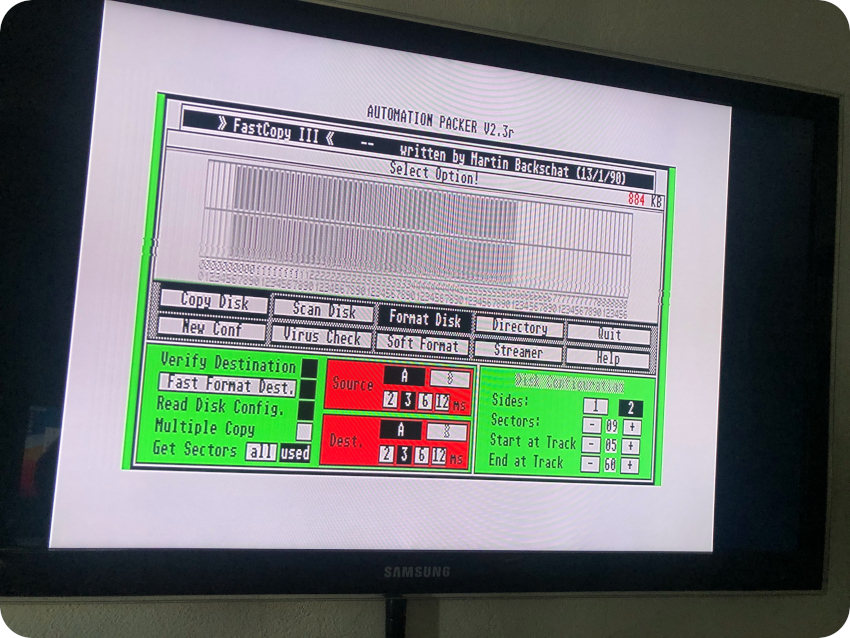
The Atari ST formats disks with a geometry of 9 sectors per track, 80 tracks, 2 sides. I used FastCopy III on the Atari ST to format disk with unusual amounts of sectors and / or tracks. This, again, resulted in mangled data whenever I deviated from the standard geometry. Thus, I had to stick with this standard geometry.
You have to keep in mind that ST images found on the Internet often don’t use the standard geometry. Indeed, publishers often needed more than 720kB to store their apps / games on diskettes and thus often used non-standard geometries to store, say, the 800kB they needed on a single diskette, using more tracks for example.
Thus, it is interesting to check the structure of an ST image disk. This simple shell script takes an image disk (here named “image.st”) as input, and outputs its numbers of tracks and sectors (from https://www.kevinhooke.com/2014/02/02/creating-atari-st-disks-from-disk-image-files-on-linux):
#!/bin/sh
od -v -Ad -t u1 -w1 $1 | awk 'NR==20 {sl=$2} NR==21 {sh=$2} NR==25 {spt=$2} NR==27 {s=$2; print "Sides: " s " Sectors: " spt " Tracks: " (sh * 256 + sl) / spt / s; exit}'
Now, let’s imagine an ST image disk with a standard 9 sectors per track, 80 tracks, 2 sides geometry. How will I write this image back to a diskette ?
Well, since ST images are basically raw images, one could imagine to simply “dd” the disk image to the proper GNU/Linux device used by for the floppy disk drive (in my case “/dev/sda“): dd if=/mnt/atari.st of=/dev/sda
Alas, this seems to only works with internal drives and not USB ones. Indeed, I tried and failed. Nowadays USB drives are simpler than old internal one, and lack the proper intelligence to do that (thus the need for a KryoFlux device for example).
Damned. But there was a solution:
- Launch the Hatari emulator on my Mac
- Configure a GEMDOS C drive and map it to a macOS folder
- Mount the ST disk image from Hatari on the A drive
- If the disk image is not copy-protected, copy files using the GEM desktop, from the A drive to the C drive
- Since the C drive is mapped to a macOS folder, I had then access to the files from the ST image, and could transfer them to the GNU/Linux system over the network via scp
- Once transferred from the Mac to the GNU/LInux system, mount a ST-formatted diskette as MS-DOS and cp the files to it.
- Once the diskette is unmounted from the GNU/Linux system, use the diskette on the Atari ST
It is rather cumbersome but it worked !
Now, let’s see if I could streamline this process. Googling around, I found that ST images can be directly mounted on GNU/Linux. How cool is that ? The Hatari emulator was thus not needed anymore to extract files from the disk image.
My workflow for creating new diskettes for the Atari ST from image disks was thus the following:
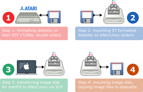
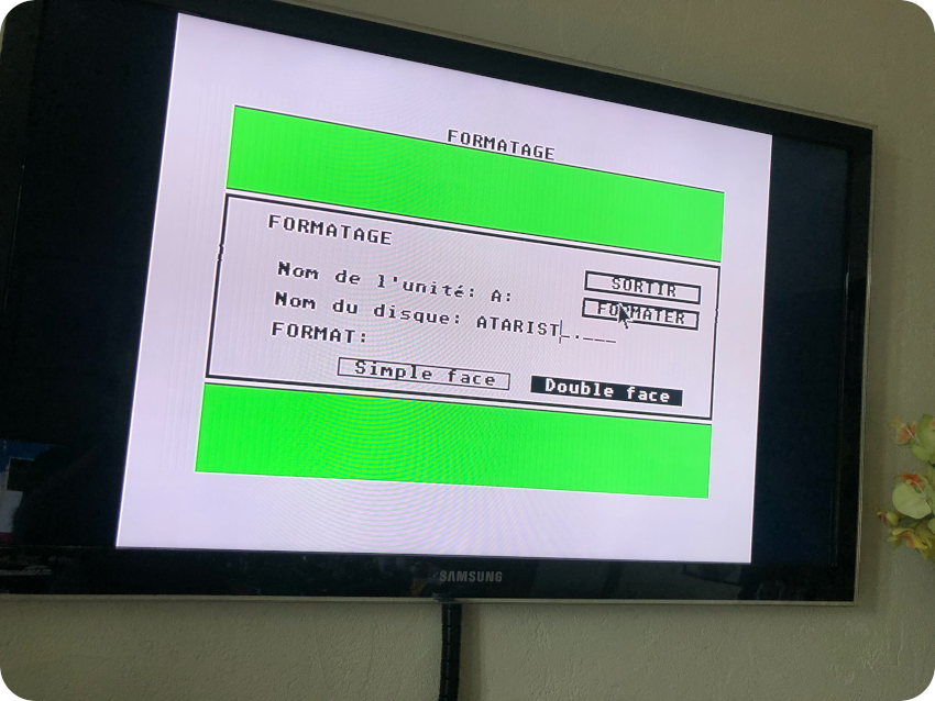
- Step 1: from GEM/TOS, formatting a diskette (standard geometry, 720kB, double sided):
- Step 2: from a GNU/Linux system, mounting the ST-formatted diskette (in my case, the Linux device for the floppy disk drive was /dev/sda). As I am using by RecalBox system, I first had to remount the filesystem with r/w rights and then create the needed mounting points (/mnt/disquette for the diskette and /mnt/image for the disk image):
mount -o remount,rw /
cd /mnt
mkdir disquette
mount  -t msdos /dev/sda disquette/
mkdir image- Step 3: from my macOS laptop, downloading an Atari ST disk image (named here image.st), testing the image with Hatari (checking that the image works and there are no copy protections), then transferring the disk image to the GNU/Linux system via scp:
scp image.st root@recalbox4k:/mnt- Step 4: via SSH, on the GNU/Linux system, mounting the image disk, then copying files from the image to the diskette mounting point, then unmounting the image and the diskette:
mount -o loop -t msdos image.st image/
cp -r /mnt/image/* /mnt/disquette
umount /mnt/disquette
umount /mnt/image
And it worked pretty well ! They are severe limitations though:
- This won’t work for copy-protected disk images
- This won’t work for disk images with sizes exceeding 720kB
- This won’t work for diskettes using not standard geometry (one-sided, and / or non standard number of tracks/sectors)
- This won’t work if the apps / games / system needs a boot sector
I had not problem formatting any of the New Old Stock HD 3″1/2 diskette (provided the DD hole was masked with tape). Alas, as expected, the 7 DD 3″1/2 were not in perfect conditions:
- Two of them could be two-sided formatted (standard geometry)
- Three of them could only be one-sided formatted (the other side being defective), with standard geometry
- Two of them could be two-sided formatted, but with non standard geometry (to avoid defective tracks):
For these 5 last diskettes, I had to come up with a solution:
- Use the “standard workflow” to copy files on a New Old Stock diskette (taking care no to exceed the amounts of space available on the target DD diskette)
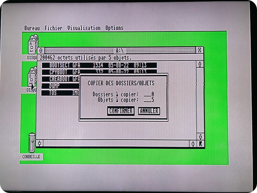
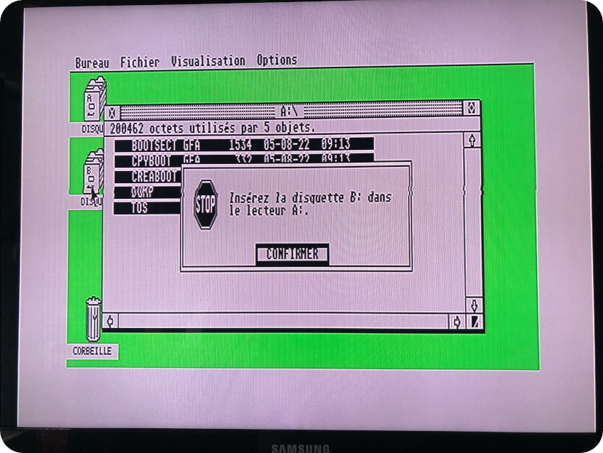
- From the GEM desktop, copy files from the A drive to the B drive. In this case, when there is no external disk drive B, the GEM let’s you copy files between diskettes (named A and B) using a single drive, swapping (a lot !) diskettes A and B when asked by the system:
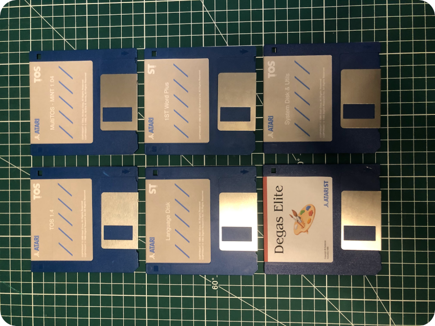
Creating labels for diskettes
In parallel of the “diskettes re-creation” process, I started “re-creating” labels for them. First, because the 20+ years old labels from the sets of New Old Stock HD diskettes would not stick any more. And second … because it is fun !
These labels are not meant to be replicas in any ways. The artwork for software at the time was mostly on the boxes and not on the diskette labels themselves. These labels are far from perfect. But I wanted to make them look as nice as I could, and somewhat “era appropriate”, with proper logos, publishers / distributors, etc.
Once again, I fired up Inkscape:
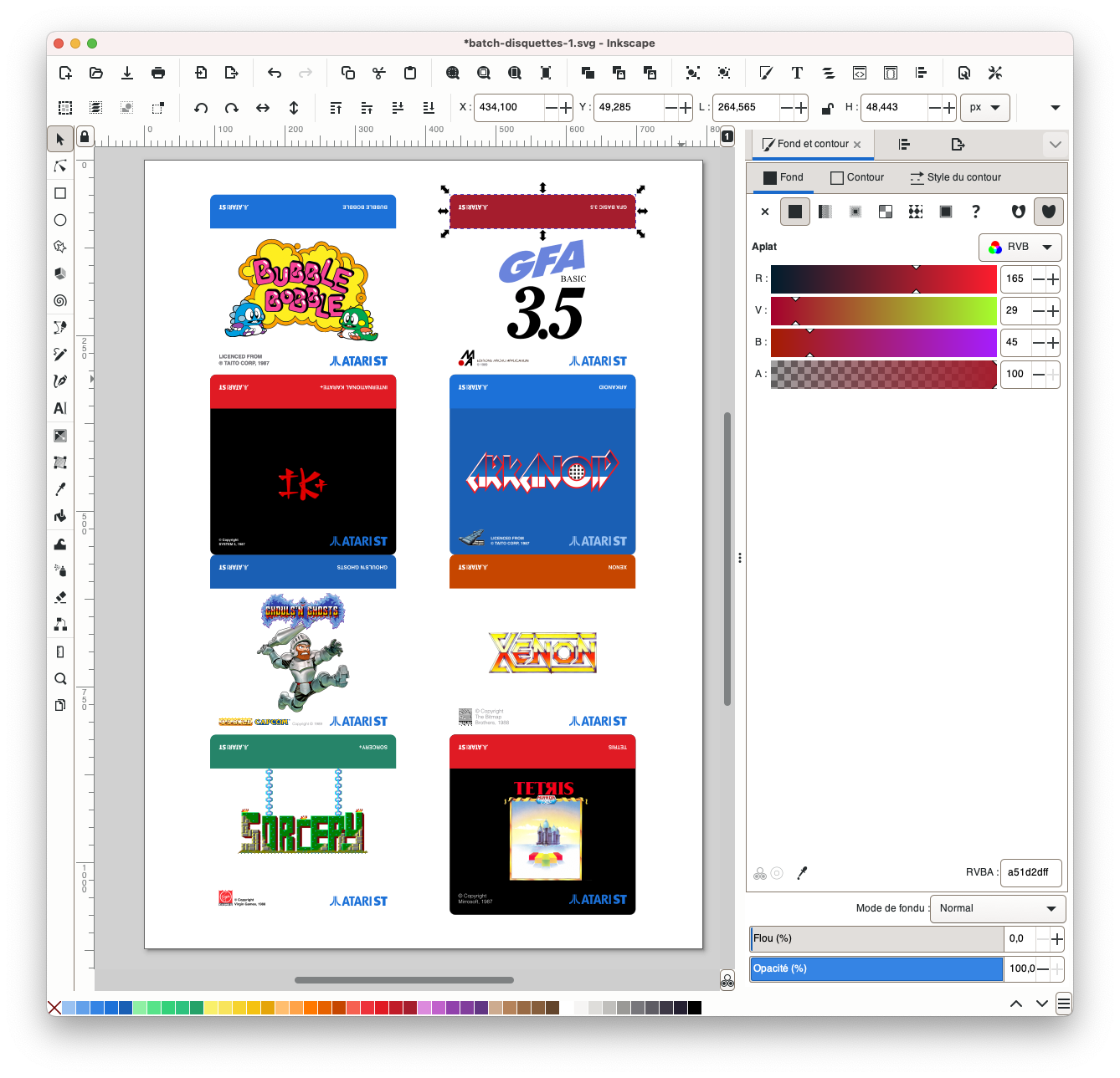
I could produce a few batches of labels, based on the model for 3″1/2 diskettes still available online on Herma‘s website:
And well … it doesn’t look that bad ! Here are a few pictures of the results:
- Labels for New Old Stock HD 3″1/2 diskettes:
- And a few labels for old DD 3″1/2 diskettes:
Games
Let’s start with the re-creation of diskettes for games. The hardest part was to work around the limitations of my process, mostly due to the use of an external USB floppy disk drive:
- No copy protection
- No funky geometry (over 720kB, etc.)
The games also had to run on TOS 1.0. So it was more a matter of finding the proper disk images, testing them, working out a solution. In some case, even if the geometry was non standard, by removing a few files (docs, etc.) I could made the game to fit into a standard 720kB diskettes. I had a small number of diskettes, so I mostly focused on games that would fit on a single diskette.
With these severe limitations, there were of course very good games that I was not able – at least for now – to put on diskettes:
- The Secret of Monkey Island
- Civilization
- Turrican (I & II)
- Gods
- Ivanhoe
- Lemmings I
- …
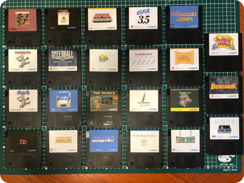
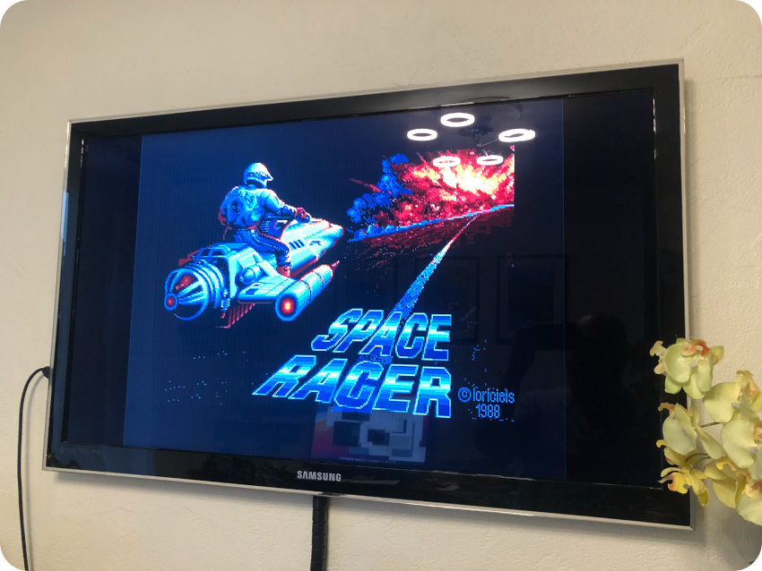
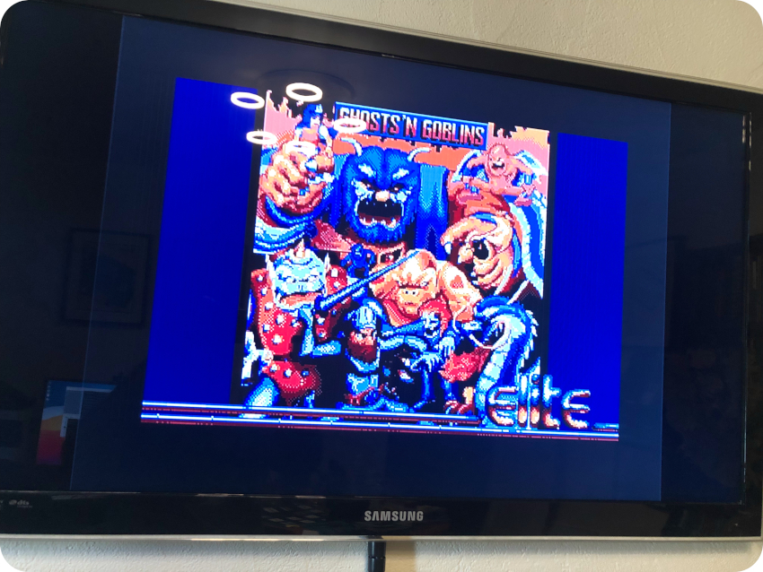
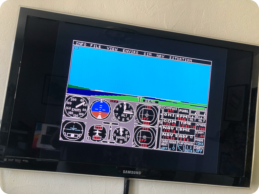
Anyway, I could re-create a set of 30+ games. Here are a few screenshots of them, running on the Atari ST, hooked to my good old Samsung TV via the SCART cable I bought:
- Space racer:
- Ghosts’n Goblins:
- Flight Simulator II
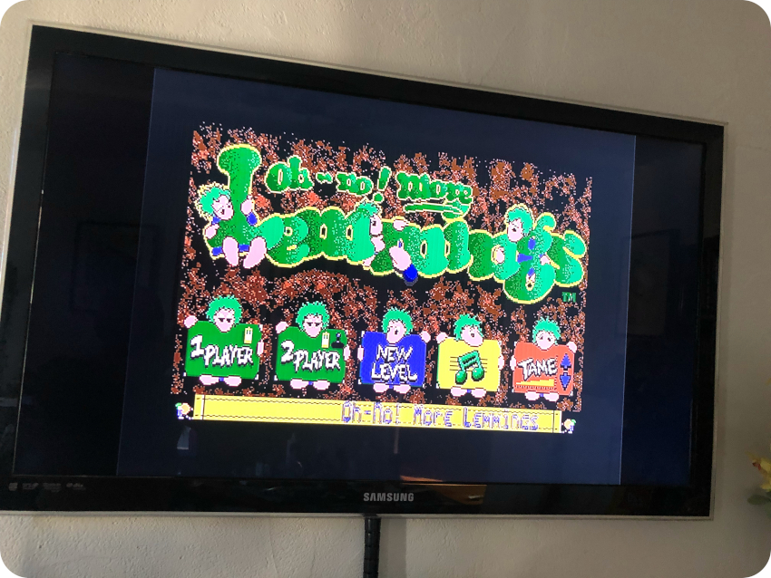
- Lemmings II (Oh no! more Lemmings)
Here is slideshow with the full set of games I could gathered and put back on diskettes (along with their corresponding re-created labels):
 Bubble Bobble (Taito, 1987))


Applications
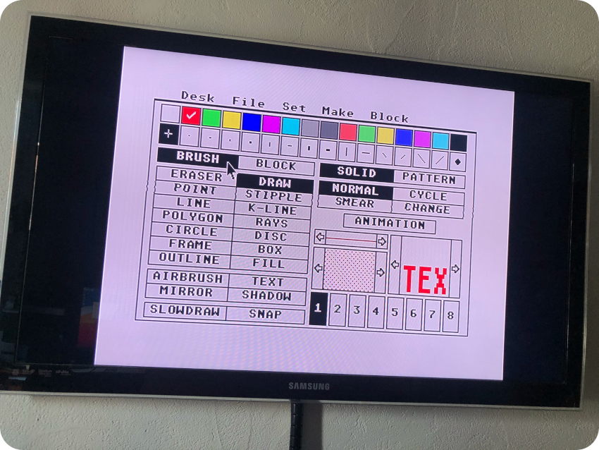
I followed the same process to re-create diskettes for applications. For some, like Degas Elite, GFA Basic or Atari Language Disk, it was straightforward:
- Finding the proper image, testing it with Hatari
- Mounting the disk image on GNU/Linux
- Mounting the diskette, copying files
Easy Peasy !
But for most of them, it was not that simple. Indeed, most of applications would only run at high resolution (640×400, monochrome).
Even though I had bought an Atari ST Mono VGA Adapter from coolnovelties.co.uk, I knew could not play with it right away. Indeed, I have a Samsung TV that cannot sync with the low horizontal scan rate of 15.75khz that is used. So, I had to come up with a workaround to make then run with my current equipment.
I found a software solution: High-Res monochrome monitor emulators. These software convert High-Res 640×400 monochrome resolution to 640×200. Of course, the results are not perfect, and it slows down a bit the system.
Several of these emulators (MonoEmus, GFA-Mono, etc.) were available at the time. I settled for SEBRA, that I had tried back in the days. There are three different modes [extract from SEBRA’s documentation]:
- The first one (“shaded” mode), converts the 640×400 monochrome screen into a 640×200 screen in three
colors. The “shaded” mode is the mode that gives the best overall view, but it is also the slowest. - The second one (“fast” mode), converts the 640×400 screen to a 640×200 screen by skipping every other scan line.
- The third one (“magnified” mode), displays 200 of the 400 scan lines. By moving the mouse you can scroll vertically.
I opted for the “shaded” mode, which gave very reasonable results. I copied SEBRA on diskette for each of the apps that required high resolution, and installed / configured SEBRA accordingly. Once done, the ST would boot from these diskettes into the (simulated) monochrome mode:
This way, I could test and re-create diskettes for a few applications. Here are a few screenshots:
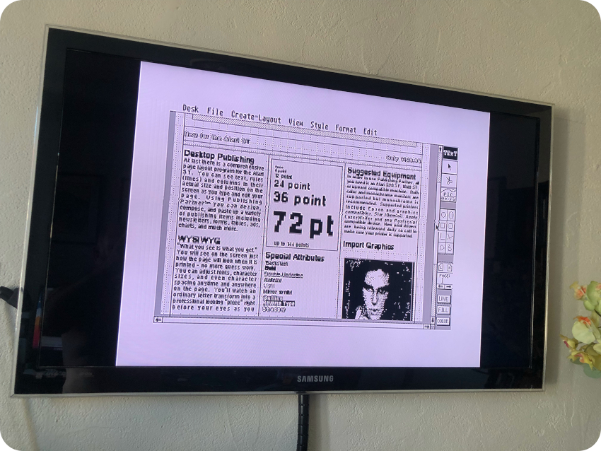
- Publishing Partner (DTP):
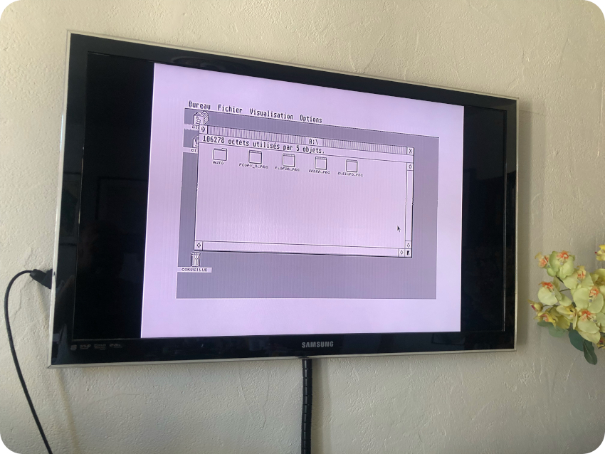
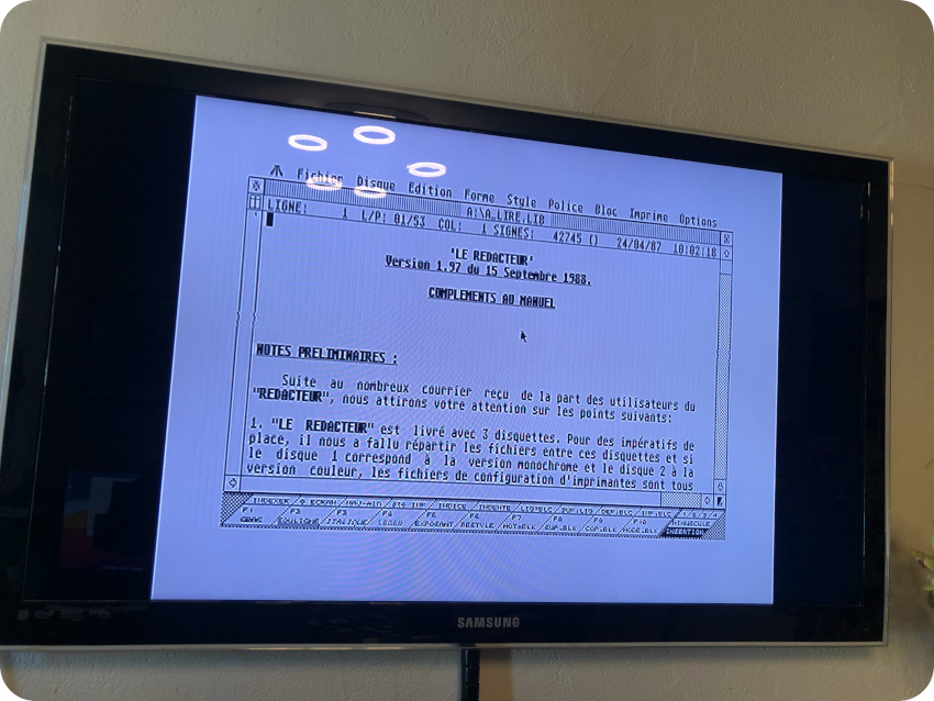
- Le Rédacteur (Word Processing):
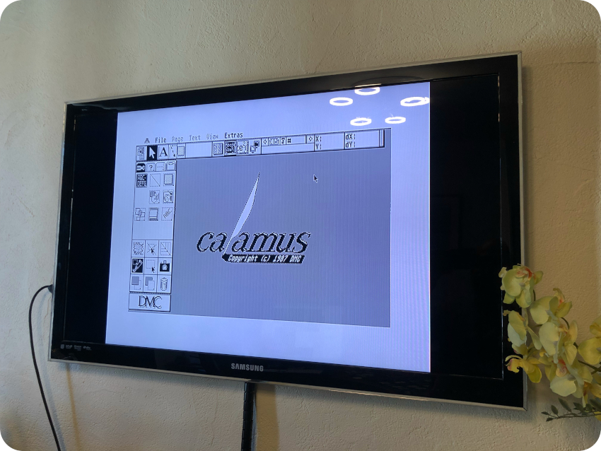
- Calamus (DTP):
Unfortunately, just like games, there were a few applications that I could not re-create:
- Signum! : this was a fantastic word processor. I loved it. Alas, it would crash or display an error message (on Hatari as well as on the actual ST hardware). The version I wanted was German only (my German is really bad) and bombed. Too bad !
- Aladin Macintosh Emulator: this was also a fantastic software. I would emulate on the ST a Macintosh (no hardware required). It worked very well. But, alas, just like Signum!, I looked everywhere, but I could only find German versions of it. It almost booted on Hatari: It passed the Happy Mac step, but would not go further the Welcome (actually, “Willkommen”) screen. It bombed on the ST hardware. What a shame …
- PC Ditto Emulator: this was also a nice piece of software that I used a lot (to run Turbo Pascal for example). It emulates a PC and let you run MS-DOS software. There were no difficulties copying and running the software itself (both in color and monochrome modes). But it requires a bootable MS-DOS diskette. I did not spent a huge amount of time on it, but I couldn’t find a way to re-create a bootable MS-DOS 3″/12 DD diskette using the external USB floppy disk drive I have (it failed miserably using Windows 10). I guess I will give it try later on …
I could nevertheless re-create a small set of apps. Here is slideshow with the ones put back on diskettes (along with their corresponding re-created labels):
 GFA Basic (Micro Application, 1989)


Systems
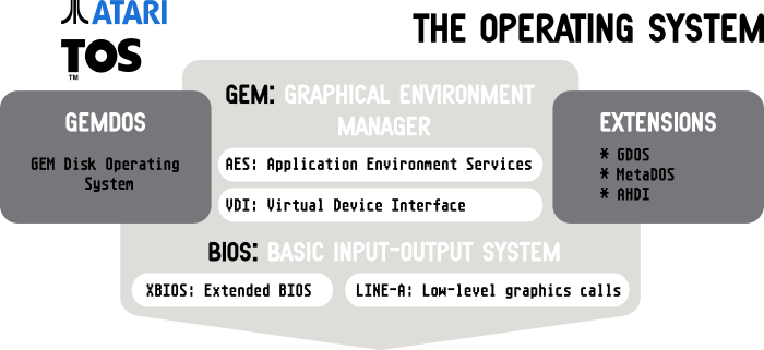
TOS is the operating system of the Atari STs. Unlike what popular belief says, TOS stands for “The Operating System” and not “Tramiel Operating System”.
It is composed of these main parts [figure inspired by https://fr.slideshare.net/fredericsagez/atari-st-histoire-de-los]:
Let’s have a look at these components:
- GEM : The GEM (Graphical Environment Manager) is the Desktop Environment of the Atari STs. It was created by Digital Research. The GEM Desktop sits on top of the GEM. The GEM itself is composed of two main parts:
- VDI: It is the core graphics system of the overall GEM engine. It is responsible for “low level” drawing in the form of “draw line from here to here”. VDI includes a resolution and coordinate independent set of vector drawing instructions which were called from applications through a fairly simple interface. VDI also includes environment information (state, or context), current color, line thickness, output device, etc. [from Wikipedia]
- AES: It provides the window system, window manager, UI style and other GUI elements (widgets). AES performs its operations by calling the VDI. Nevertheless, the two parts of GEM were often completely separated in applications. Applications typically called AES commands to set up a new window, with the rest of the application using VDI calls to actually draw into that window. [from Wikipedia]
- GEMDOS (Disk Operating System): the GEMDOS is a DOS-like system. Its machine independent functionalities are responsible for handling high level tasks for running programs and managing I/Os.
- BIOS: The BIOS is responsible for access to peripherals and memory (availability test, reading and writing, …). Using BIOS calls, one can read and write to, and get the status of, the serial port, the midi port, the parallel port, the disks, and the screen/terminal.
- XBIOS: This layer makes it possible to manage and control peripherals. Its functionalities control the sound chip, the floppy disks, the serial port, the mouse, and the midi port. GEMDOS is also built from these calls.
- LINE-A: These are low level high-speed graphics calls. In principle, one should not call these routines directly. But I remember doing so nevertheless, they were so damn faster.
- Extensions: the system can use extensions, loaded separately. GDOS (Graphics Device Operating System) was one of these extensions. It was used by Word Processor and DTP software to manage fonts, and metafiles. MetaDOS was used by devices not supported by the GEMDOS, like CD-ROM drives. AHDI (Atari Hard Disk Driver) was used for Hard Disk drives.
Except for very early ST models, GEM/TOS was built in ROM. There were no need for these machines to boot from a floppy disk. Unless you wanted to run a different TOS version than the built-in one. Or if you wanted to run extensions (like GDOS). Or … if you wanted to speed-up the booting process. When no disk are inserted, the ST waits around 30 seconds before launching the GEM Desktop. With a formatted diskette inserted, it boots right away.
Different versions of TOS were available. Here is a list of the ones that could be run by an Atari 1040 ST/STF/STFM:
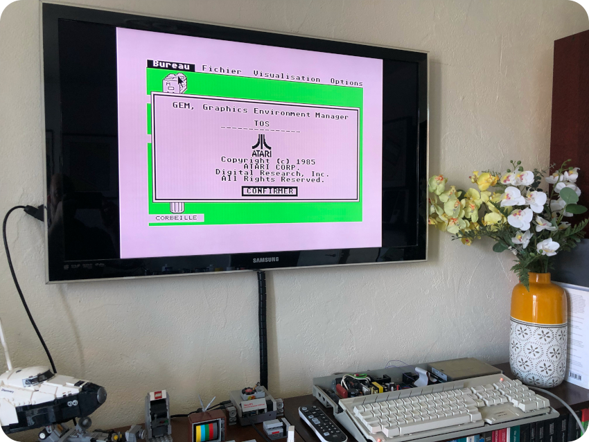
- TOS 1.0 (ROM TOS, 1985) – For Atari 520/1040 – The original ROM TOS shipped in 520 ST and 1040 ST machines.
- TOS 1.02 (MEGA TOS, 1987) – For Atari 520 ST, 1040 ST, Mega ST (1, 2 & 4) – Bug fixes, support for the Blitter co-processor and RTC. Nicknamed “Mega TOS” because if was the first TOS supporting Mega ST machines.
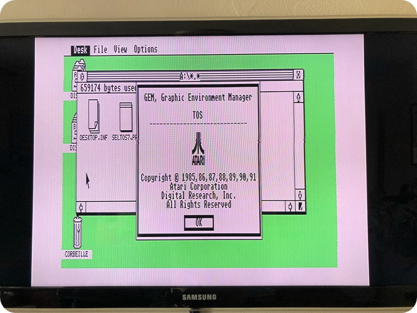
- TOS 1.04 (RAINBOW TOS, 1989) – For Atari 520 ST, 1040 ST, Mega ST (1, 2 & 4) and Stacy – Bug fixes, file selector changes, DOS-compatible disk formatting, improved performance. Nicknamed “Rainbow TOS” because of the unusual rainbow colors of the Atari logo in the Desktop “About” box. TOS 1.04 was actually named 1.4 first, before being renamed 1.04.
- TOS 2.06 (No nickname, 1991) – For Atari 520 ST, 520 STE, 1040 ST, 1040 STE – This is the last version of TOS available for the ST/STE range of computers – Bug fixes, 1.44 MB diskette support, GEM enhancements, IDE Hard disk booting, Atari logo display at boot-up, memory test during cold boots.
There were many other releases, but not compatible with the ST range of Atari computers (aiming at Sparrow, ST Book, TT, Falcon, etc.).
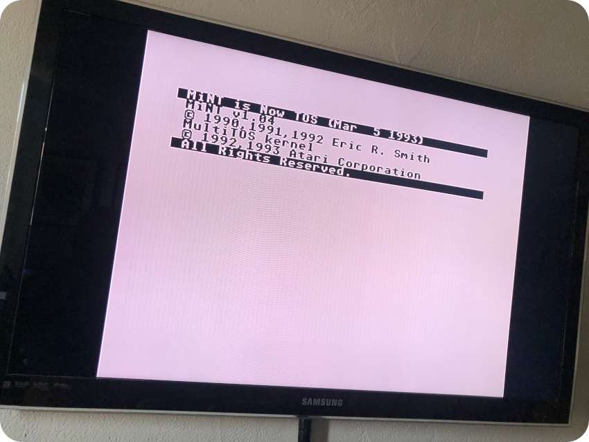
True multitasking was originally not supported. MultiTOS (MiNT / “MINT is Now TOS”) was developed by Eric Smith to allow TOS to preemptively multitask (it started in 1989, was released in 1993). Originally released as “MinT is Not TOS”, the new kernel got so much traction that E. Smith was hired by Atari. MiNT was adopted as an official alternative kernel for the Atari Falcon and released as “MiNT is Now TOS”. After Atari went belly up, MiNT development continued under the name FreeMiNT, and is still actively maintained by an open source community.
A minimal install of MiNT can actually run on an Atari 1040 ST.
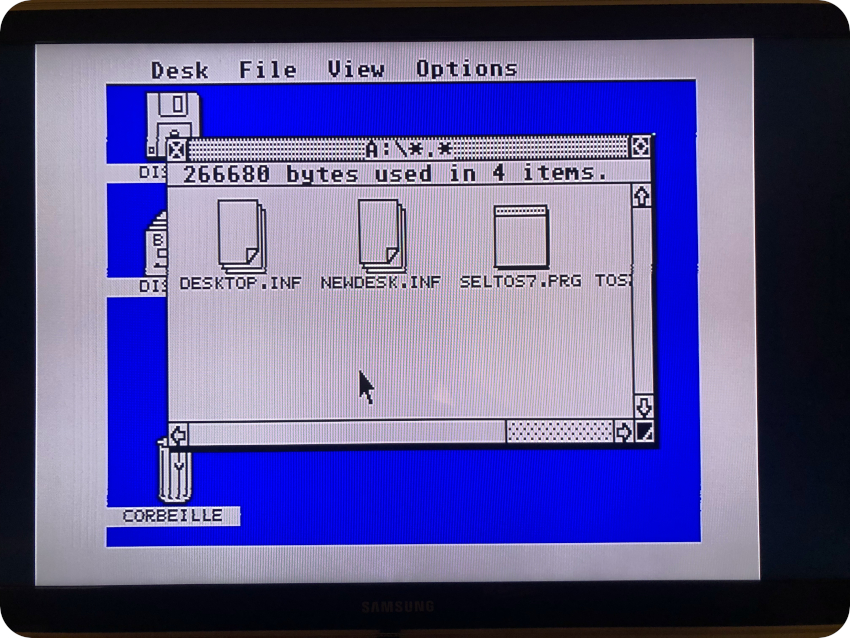
TOS 1.0
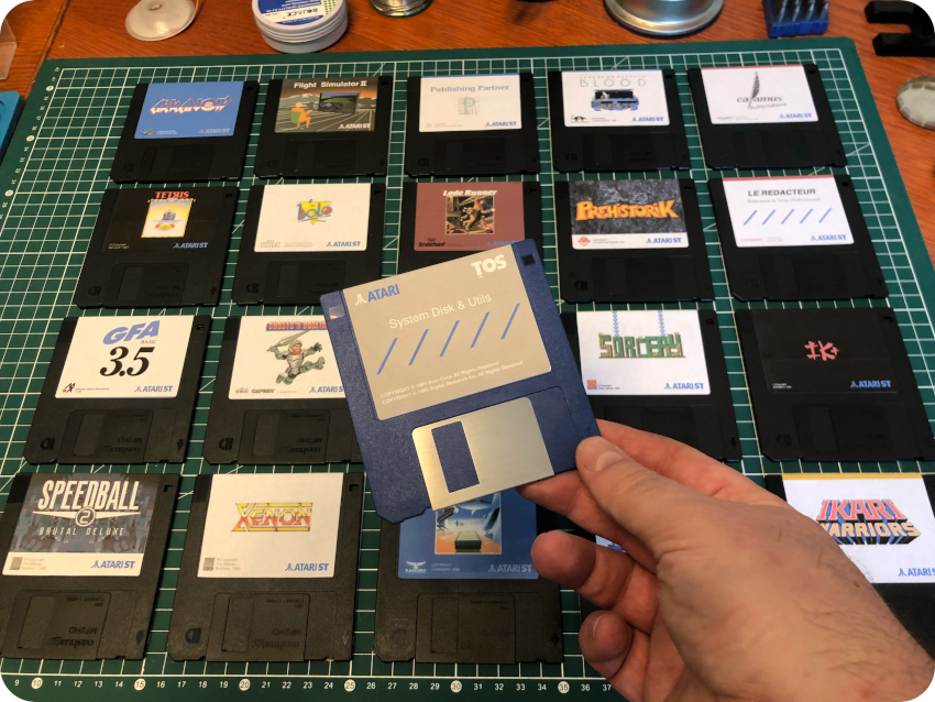
Let’s re-create system diskettes, starting with TOS 1.0. There is in fact no need for a diskette to boot the Atari ST. Nevertheless, it is helpful, since it shortens the boot process, and can be used to store system utilities and / or extensions.
So … this “System Disk” is actually an Atari ST formatted disk with a few utils:
- SEBRA : so I could simulate a monochrome High-Res display
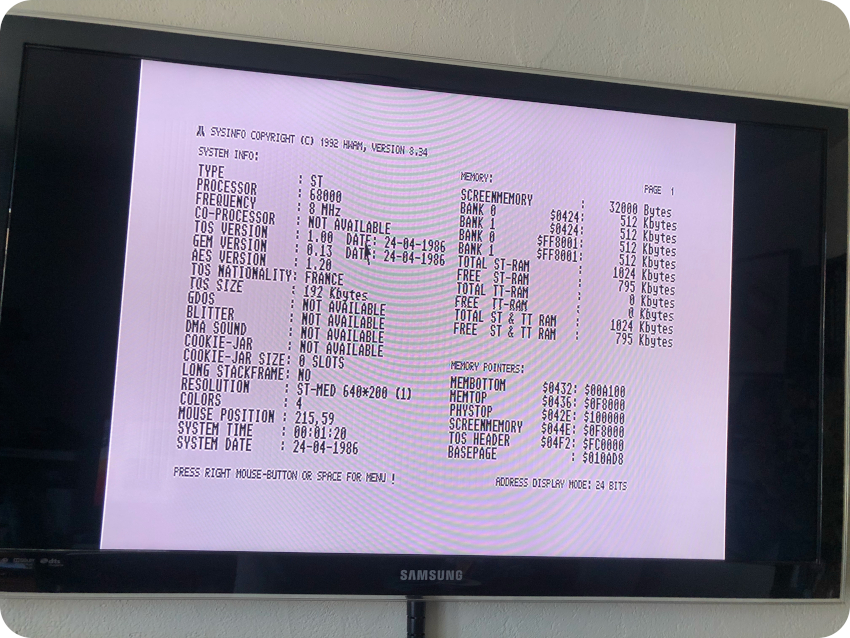
- SysInfo: to get detailed system information
- FastCopy III: to copy / format diskettes
- FLOFOR: a floppy formatter by PP (P.Putnik), with very flexible parameter settings.
Here is the mandatory screenshot:
And here is a screenshot of SysInfo outputs:
TOS 1.04 (a.k.a Rainbow TOS)
Creating a System Disk for TOS 1.04 (Rainbow TOS) is much more challenging. It is easy to find ROM images, but not disk images. Fortunately, there is one available. It is actually a pre-release of the French version. It is numbered 1.4 and not 1.04.
But there are slight problems:
- The image disk corresponds to a one-sided DD diskette (and I cannot directly write to one-sided diskette with my external USB 3″1/2 floppy disk drive).
- The disk image only contains the .IMG file of the ROM, plus a boot loader. And I cannot copy a boot sector without a specific tool.
My usual copy workflow won’t work there. So, I came up with this (cumbersome) solution:
- Format a one-sided DD diskette from the Atari ST (360 kB)
- Format a two-sided DD diskette from the Atari ST (720 kB)
- On my Mac, launch Hatari and mount the TOS 1.4FR disk image
- From Hatari, using the Desktop, copy the .IMG file from the disk image to a shared GEMDOS drive
- Create a GFA Basic program that would read the boot sector and dump it to the shared GEMDOS drive
- Create a GFA Basic program that would load the dump dile and write it back to a disk as a boot sector
- Save the GFA Basic programs to the shared GEMDOS drive
- Transfer the GFA Basic programs, the boot sector dump and the .IMG file via scp
- From the GNU/Linux box copy them to the two-sided diskette
- From the Atari ST, copy files from the two-sided diskette to the one-sided diskette. The one-sided diskette now contains the file dump of the boot sector, the .IMG file and the needed GFA Basic code
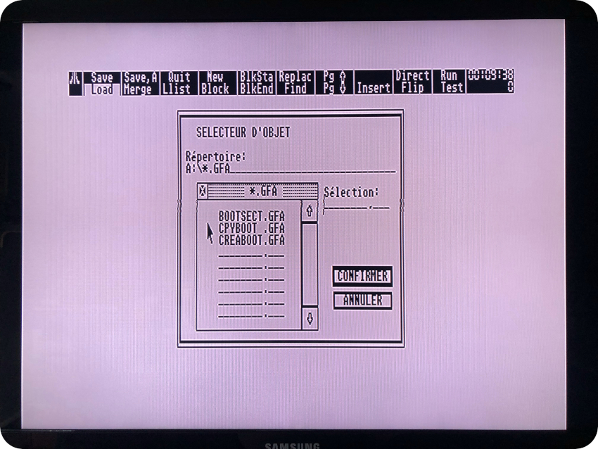
- Launch the GFA Basic from its own previously re-created diskette.
- Insert the one-sided diskette, run the GFA code, which writes a boot sector from the saved dump
This sounds like a plan !
Why GFA Basic ? Because I used it a lot back in the days, it would be fun to code with it again !
How to read and write a boot sector ? Using XBIOS calls of course !
- Floprd (XBIOS 8) – Read individual sectors from floppy disk: r%=XBIOS(8,L:b%,L:f%,d%,sec%,t%,side%,n%)
- r% : 0 if no error
- b% : address of the area from which sectors are read
- f% : unused
- d% : drive number (0=A, 1=B etc)
- sec% : sector number
- t% : track number
- side% : disk side (0 or 1)
- n% : number of sectors to be read
- Flopwr (XBIOS 9) – Write individual sectors on a floppy disk: r%=XBIOS(9,L:b%,L:f%,d%,sec%,t%,side%,n%)
- r% : 0 if no error
- b% : address of the area to which sectors are written
- f% : unused
- d% : drive number (0=A, 1=B etc)
- sec% : sector number
- t% : track number
- side% : disk side (0 or 1)
- n% : number of sectors to be written
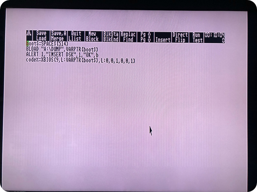
Here is the (crude) GFA Basic code used to load the boot sector into memory and save it as a binary file named “DUMP”:
 Here is the content of the extracted boot loader:

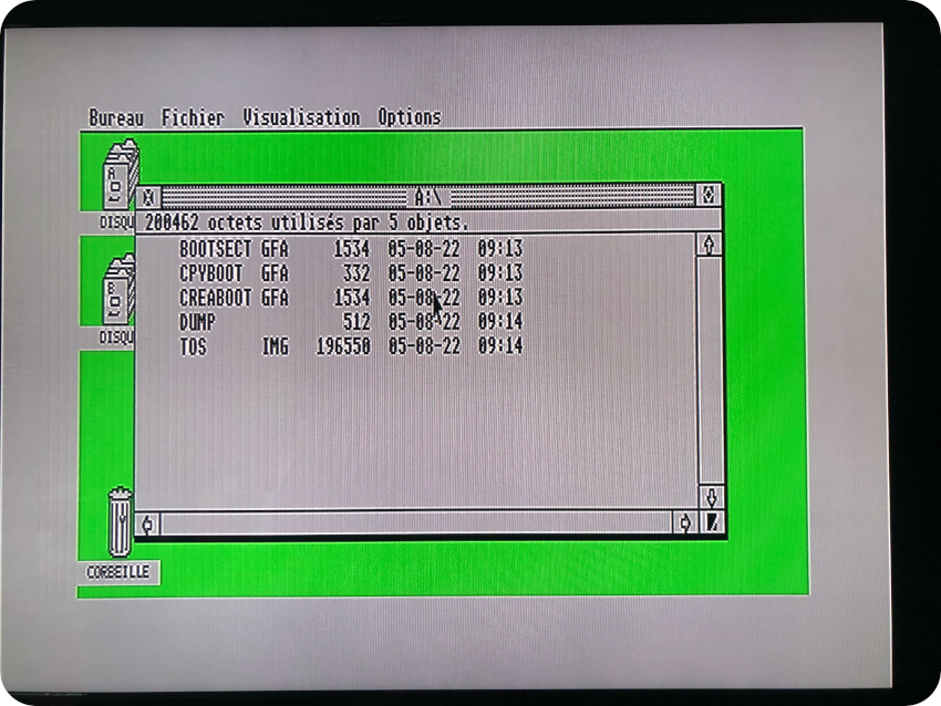
Here are the files copied on the target DD 3″1/2 diskette:
Here are a couple of screenshots of the GFA Basic code running on the ST, used to read the boot loader dump and to write it back on a boot sector:
And … it freakin’ worked ! (© Adrian Black)
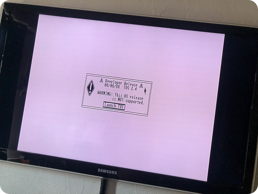
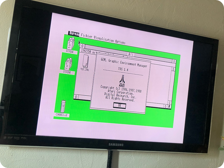
Cool ! I now have a 1.4 TOS system disk (i.e. pre-release of TOS 1.04)
TOS 2.06
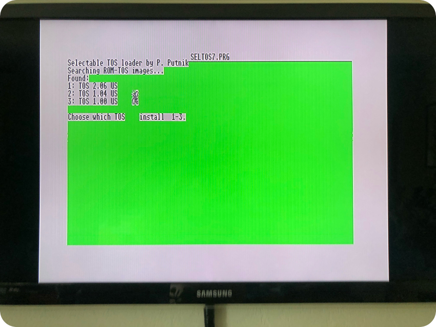
Now, let’s try to re-create a TOS 2.06 system disk. This time, there is no disk image available at all, only ROM images. Thankfully, PP (P. Putnik) comes to the rescue with SELTOS.
SELTOS allows usage of different TOS versions by running it in RAM. SELTOS looks for supported ROM image in the current diretory (up to 9) and allows the selection of which to install. The supported ROM images are V. 1.00, 1.04 and 2.06. UK, US, German and Swedish (Only 2.06). Unfortunately (for me), no French images are supported.
So, I downloaded US versions of TOS 1.0, 1.04 and 2.06 and gave it a try (copying SELTOS and the ROM images on a ST formatted diskette):
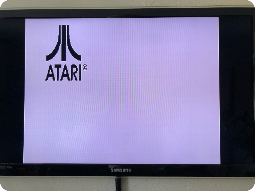
I installed TOS 2.06 US. Here are a couple of screenshots:
- Booting TOS 2.06
- TOS 2.06 Desktop (320×200 resolution)
- TOS 2.06 Desktop (medium resolution, about box)
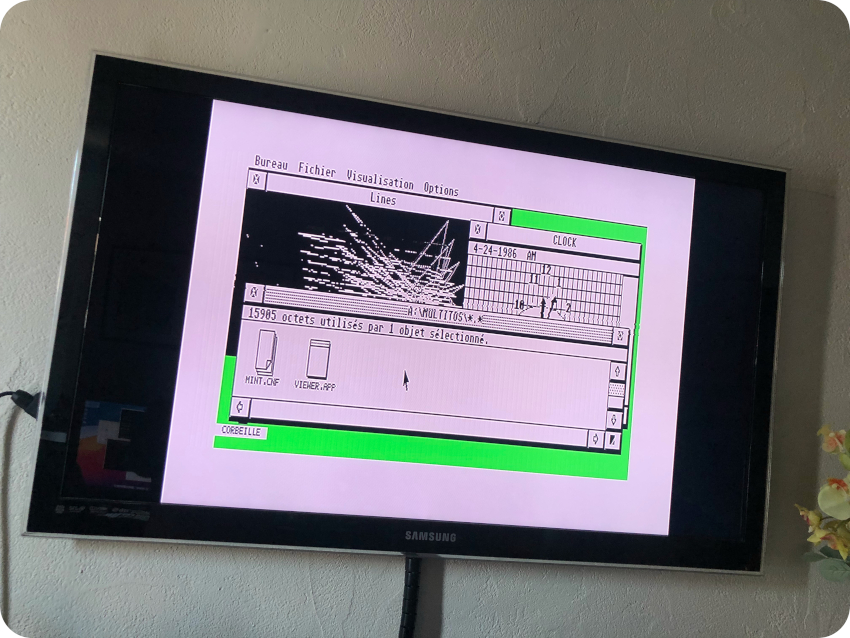
MultiTOS/MiNT
Now, let’s give a try to MultiTos (MiNT 1.04). It was very easy, since already made disk images are available (including a French one). I followed my usual workflow. Here are the results:
- Booting MiNT:
- MiNT Desktop (Low resolution)
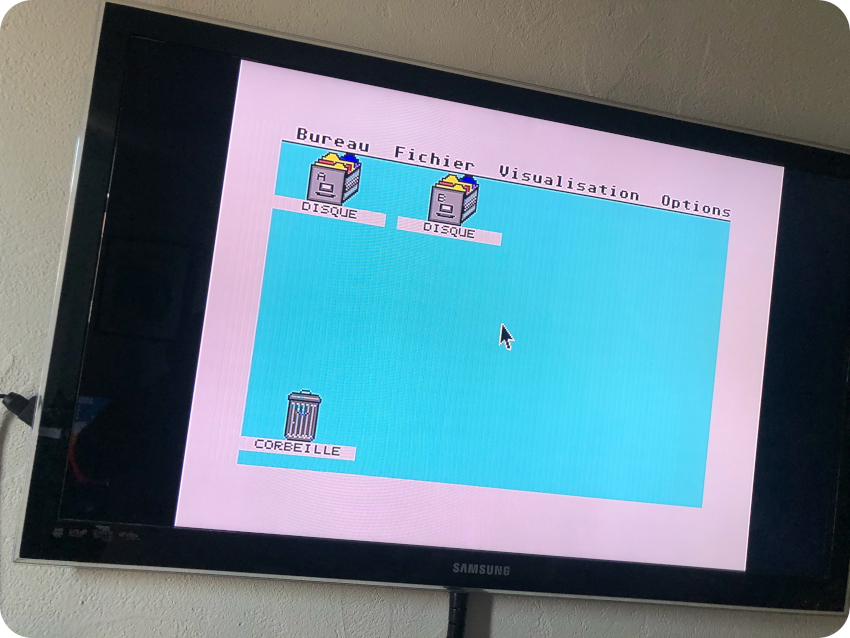
- MiNT Desktop at medium resolution, multistaking !
Here is slideshow with the System Disks that were put on diskettes (along with their corresponding re-created labels):
 System Disk - TOS 1.0 (Atari Corp, 1985)


Next steps
All in all, it took me a almost two months to get there. What are the next steps ? Well, there is still things I would like to improve and / or experiment with the Atari ST:
- Maybe recapping the PSU,
- Adding an UltraSatan external disk (SD cards),
- Playing with an OSSC upscaler, and see if i can get it to display Hig-Res 640×400 on my Samsung TV
- Get a better joystick !
And then … I have other retro-computing projects in mind. I have to deal with the fact that there is not much room left in my study. So I will probably opt for a small-sized oldie. May be one of these:
- Oric Atmos or Oric-1: I almost got an Oric-1 when I was a kid (I went for the Amstrad CPC in the end) and I had a school friend that had an Atmos (which is mostly an Oric-1 with a very cute case and a much nicer keyboard)
- Matra Alice 32 or Alice 90: Ok, these are NOT good computers. These french 8-bit computers are nothing but TRS-80 MC-10 clones. They flopped badly. But … they are so cute ! And they usually come with fantastic documentation and illustrations by Mœbius (Jean Giraud) !
May be I will take another path. Either explore … the “dark side”:
- Commodore 64: I was definitely on team Amstrad !
- Commodore Amiga: I was definitely on team Atari ST !
or … try to find Unix-based workstations I used to work with:
- NeXT Cube or NeXT Station (that would be a dream !!)
- HP9000 series 300 or 400 (they are quite difficult to find)
Time will tell ! For now, I am gonna take a (small) break from retro-computing. I have quantum computing related projects to finish (including a 300+ page deep dive presentation which is almost ready)
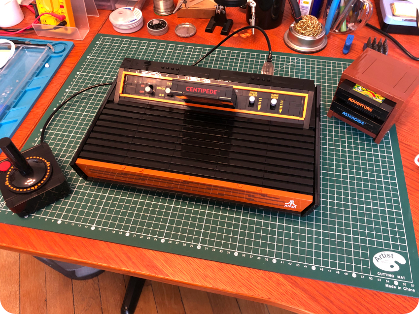
And … I caught the Lego fever about a year ago. Oh well, I guess my next post will be about that. And, of course, I bought and built the Atari 2600 Lego set:
Acknowledgments and links
As usual, I am deeply indebted to the retro-computing community. Here are a few thanks and links:
Emulation:
- Hatari: https://hatari.tuxfamily.org/
Communities and dedicated web sites:
- P. Putnik: https://atari.8bitchip.info/
- Info-coach (DrCoolZic): https://info-coach.fr/atari/index.php
- JLG: https://jlgconsult.pagesperso-orange.fr/Atari/
- La Bible Atari: http://www.labibleatari.fr/ (french)
- Atari Forum: https://www.atari-forum.com
- TOS.hyp: https://freemint.github.io/tos.hyp/en/index.html
- Exxos Forum: https://www.exxosforum.co.uk/forum/index.php
- MO5: https://mo5.com/site/atelier-de-mo5-premiers-soins-de-latari-st/ (french)
- Atari4ever (Atari ST hardware hacks): http://atari4ever.free.fr/
Youtubers:
- ctrl-alt-rees: https://www.youtube.com/c/ctrlaltrees
- Vretrocomputing (french): https://www.youtube.com/c/Vretrocomputing
- Adrian’s Digital Basement: https://www.youtube.com/c/adriansdigitalbasement
- Mr Luch’s Things: https://www.youtube.com/c/MrLurchsThings
- RMC – The Cave: https://www.youtube.com/c/RMCRetro
- Rodrik Studio (french): https://www.youtube.com/c/RodrikStudio
- Jan Beta: https://www.youtube.com/c/JanBeta
Software:
- Atari Mania: http://www.atarimania.com
- Atari ST Essential Software: https://sites.google.com/site/stessential
- Planet Emu: https://www.planetemu.net/machine/atari-st
Books:
- The Anatomy of the ATARI ST, by K. Gerits, L. Englisch and R. Bruckmann (Data Becker Book)
- Faster Than Light: The Atari ST and the 16-bit Revolution, by J. Lendino (Steel Gear Press)
Thoroughly presented and interesting article. Odd that you can do low res but not high res. The EZIO 2436w can display both except the low/med res displays out of range in top right- but still displays. I got on 2nd hand for £44 delivered. You can see output on my YouTube channel. I made a switchable cable – alas one gun wire needs resoldering on low res.
Thanks for posting the image to disk steps. Likely I will add a Gotech plus mod to allow A/B boot and like you said an UltraSatan or HD. I guess at a push one could create a modem cable and tip into ST from Mac? I used to use my ST as a Unix terminal back in the day like that.
Keep having fun.
Nostalgie 😉
Je confirme que le switch ressemble beaucoup à celui que j’avais sur mon 1040 STF et qui de mémoire permettait de mettre d’utiliser une seule disquette double face pour des jeux initialement sur des disquettes simple face
Wonderful article. I just bought myself an untested 1040stfm (probably an stfm as I can see an RF cable on the picture) with an SM124 monitor. Unused for 30 years or so.
I was planning on more or less the same as you have done here but with an external Gotek and boot switch mod. I love what you did with the diskettes and I think I will steal your idea on that.
A pure retro nostalgia project.
BR,
Henrik
Thank you so much !
Superbe article : j’ai moi même en 2024 remis en état un ATARI STE avec remplacement de l’alimentation par une alim moderne 2024, rajout de 4Ko RAM ajour disque externe ACSI2STM, remise en peinture de la coque mais en RAL 7038. Pourriez vous je vos prie partager vos “Template” de disquette, car je suis assez tenté d’en refaire certaines. Un partage de l’étiquette sous l’Atari serai aussi très utile. Merci
L’Atari STE mon premier ordinateur personnel.